


By default, the Additive application creates supports automatically for your part. It is important to understand how these automatic supports are implemented. The application simulates the build process with an initial set of supports based upon geometry considerations only (that is, a user-specified overhang angle), and then generates two new sets of optimized supports based upon the simulation results. The initial supports, called Uniform Volumeless Supports, are thin, single-bead width support walls placed uniformly underneath overhang areas defined by Minimum Overhang Angle. The maximum residual stresses that supports must withstand are predicted in the simulation (in the Mechanics Solver). The optimized support structures are then automatically generated (in the support generation module) based upon an algorithm that varies the support density to carry these maximum residual stresses. Two sets of optimized supports are generated:
Optimized Volumeless Supports are of a uniform wall thickness (single-bead width), but wall spacing is varied such that more walls are placed in regions of higher residual stress and fewer walls in regions of lower residual stress.
Optimized Solid Supports are uniformly spaced walls with varying thicknesses such that thicker walls are placed in regions of higher residual stress and thinner walls in regions of lower residual stress.
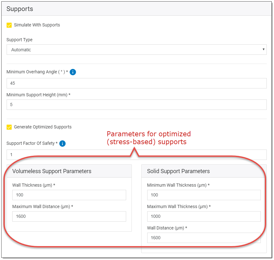
On your simulation form, you will need to specify certain parameters that guide the support generation process.
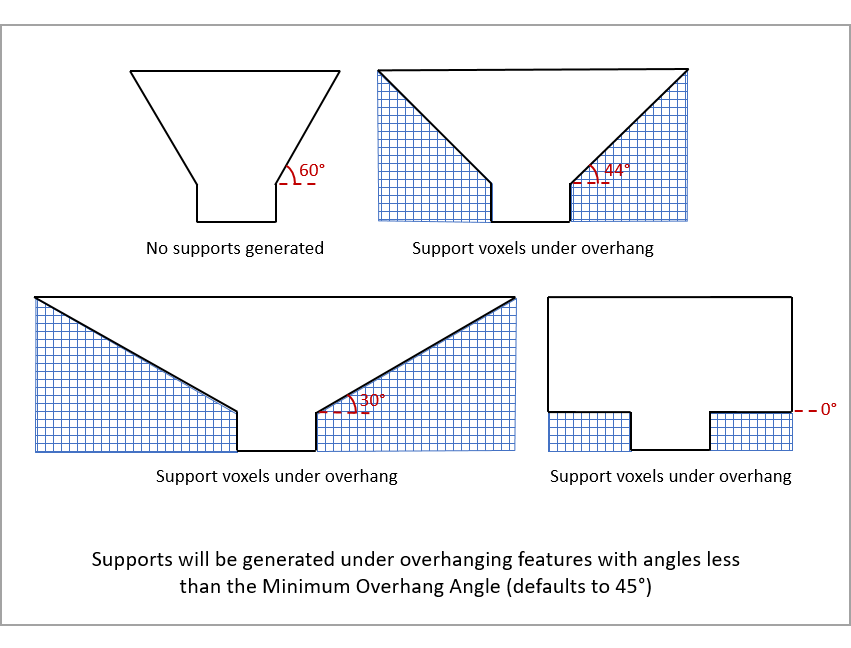
Minimum Overhang Angle (°) - The overhang angle is measured from the powder bed surface (horizontal = 0 degrees) up to the surface of the part. Any point on the surface of the part having an angle less than the Minimum Overhang Angle will be supported. The default Minimum Overhang Angle is 45 degrees. Avoid using a value that is the same as the angle of the geometry of your part, as it can cause asymmetric support structures due to finite rounding errors. For example, if your geometry includes an overhanging feature of precisely 45 degrees, use 46 or 44 degrees for Minimum Overhang Angle.
Supports will be created for overhang areas even in cases where the supports cannot reach the baseplate because a portion of the part is in the way. In that case, supports will span part-surface to part-surface. We call these part-to-part supports.
Minimum Support Height (mm) - This is the height, in millimeters, that the part will be elevated off the baseplate. For example, if you set a value of 3 mm then the part will be elevated such that the lowest point on the part is at least 3 mm above the baseplate. This value should be set to allow for an easy part cutoff from the baseplate while also considering how many voxels must be created to add that additional height. (More voxel layers = more simulation time.) We recommend that this value be set as low as is realistic for each simulation. The default value is 0. (See Simulating Without Supports)
Support Factor of Safety - The Support Factor of Safety is a parameter that drives the strength of the automatically generated optimized support structures. If you would like the supports to withstand 2x the expected load, then you would enter a 2 in this field and the predicted strength of the automatically generated support structure would be double the predicted stress. The strength of the support structure is driven by the number and thickness of support walls that are generated. The default Support Factor of Safety is 1.
Volumeless Support Parameters
Wall Thickness (μm) - A parameter used for the optimized volumeless supports. It is the wall thickness of the generated support walls.
Maximum Wall Distance (μm) - Maximum Wall Distance is a parameter used for the optimized volumeless supports. It is the allowed maximum distance between two neighboring support walls. Regardless of the predicted stress level in the support structure, the walls in supported regions will be spaced not more than this value. Too large of a wall distance might result in failures such as the part breaking away from the support or the development of cracks in the support structure. When a laser scans a relatively large area of powder where the support wall distance is too wide, cracking might happen since powder has no strength to hold the solidified part in place. The excessive distortion might cause blade and part collision. We recommend that Maximum Wall Distance should not exceed 2 mm when a volumeless (single bead) support wall is used.
Solid Support Parameters
Minimum and Maximum Wall Thickness (μm) - Minimum and Maximum Wall Thickness are parameters used for the optimized solid supports. Minimum Wall Thickness is the thinnest possible support wall that the machine will build. Usually you will specify the thickness of a single bead scan. The default value is 100 microns. The thickness of support walls will not exceed the Maximum Wall Thickness. The default value is 1 mm.
Wall Distance (μm) - A parameter used for the optimized solid supports. It is the distance between support walls.
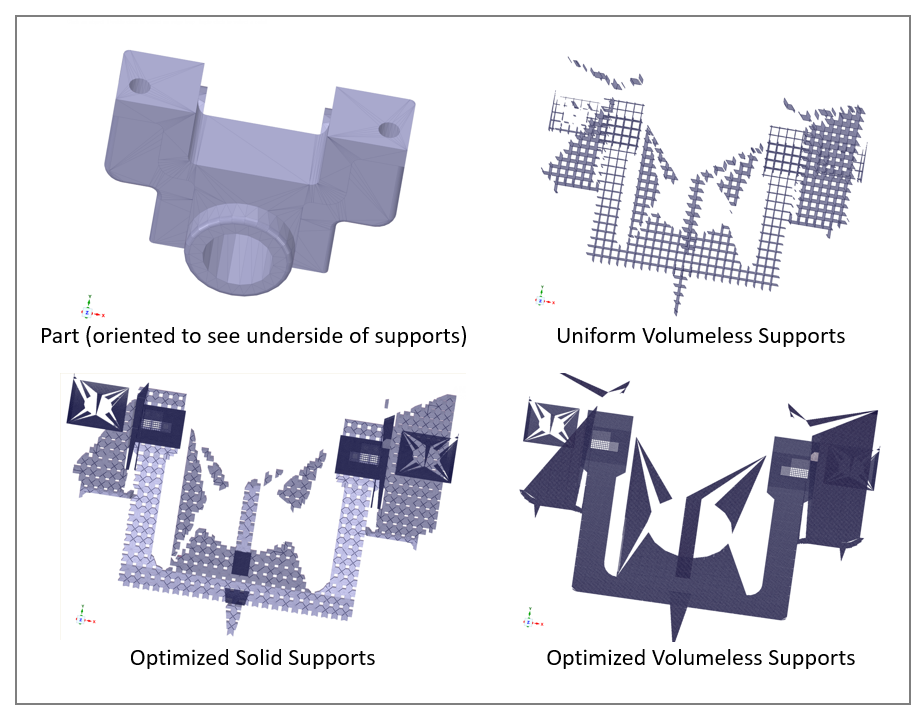
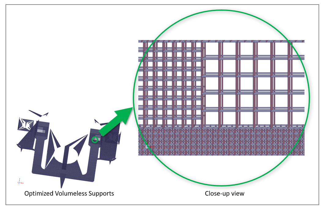
The following figure shows the bevel gear example with all three sets of supports generated with the automatic supports option using default settings. A close-up of the optimized volumeless supports is also shown.
Disabling Support Optimization
If you don't care about optimized supports, clear the Generate Optimized Supports check box to disable the feature. This will result in shorter run times.
The time to perform the support optimization function is related to the number of triangles (facets) in your geometry. The more triangles, the longer support optimization will take. This may be especially noticeable if you choose the distortion compensation output option that produces a distortion compensated stl file with more triangles than the original stl file.