


Once a part is available after importing, you can import supports that will be associated with that part. Click Import Support to bring up the import support window.
See Define Support Options for general information about how supports are used in the additive manufacturing process. For now, it is important to know the following:
Support files are in .stl format.
Dimensions are assumed to be in millimeters (mm).
The support must be oriented in the same 3D space as the part (aligned with the part in the X-Y plane).
Each support .stl file must be homogeneous with respect to its geometry, that is, either all volumeless supports or all solid supports, within the file. See Support STL Type.
There is no limit on the number of support .stl files that can be imported for any given part.
Create Support Groups to use multiple support .stl files for the same part in a simulation.
Lock Support to Part
Check this option to lock the position of the support with that of the part. This implies that you have created the part and supports so that they are properly aligned with respect to each other in X, Y, and Z. Then, regardless of how each geometry may have been rotated for viewing when it was imported, the application assumes they are in alignment in 3D space.
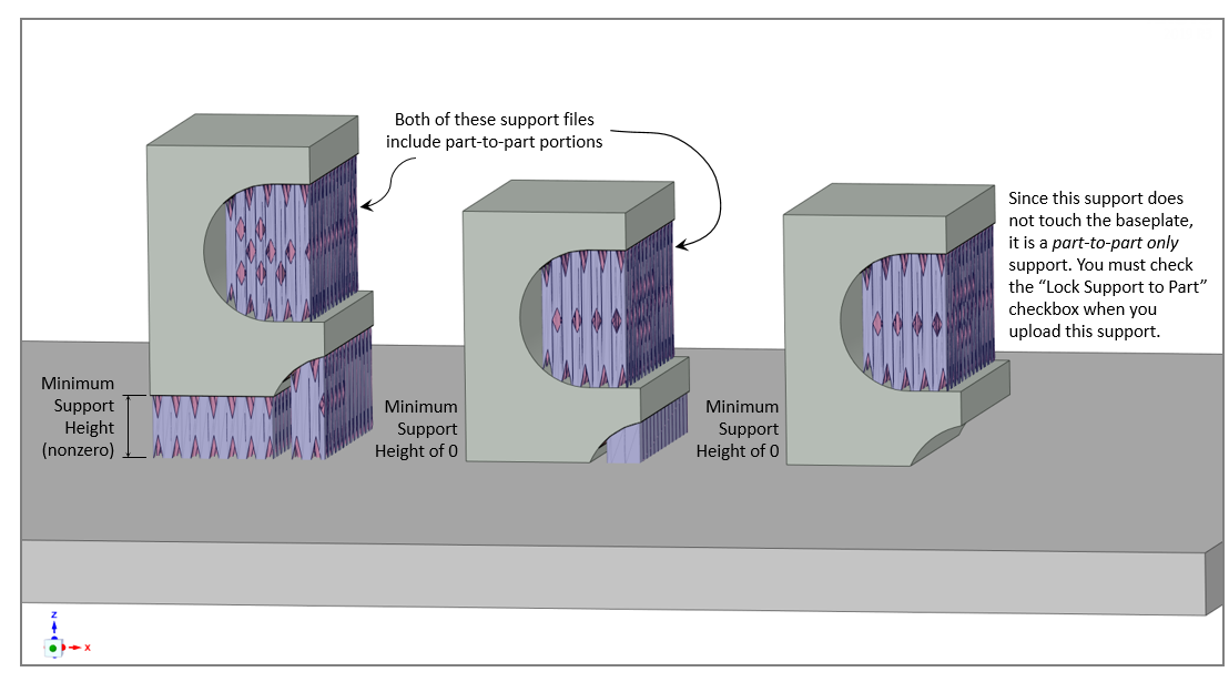
If a support is a part-to-part only support (that is, no portion of the support structure touches the baseplate), this check box must be checked to ensure proper alignment. If some segment of the support does touch the baseplate and the support and part are aligned in X, Y, and Z, this feature will automatically calculate the proper Minimum Support Height.
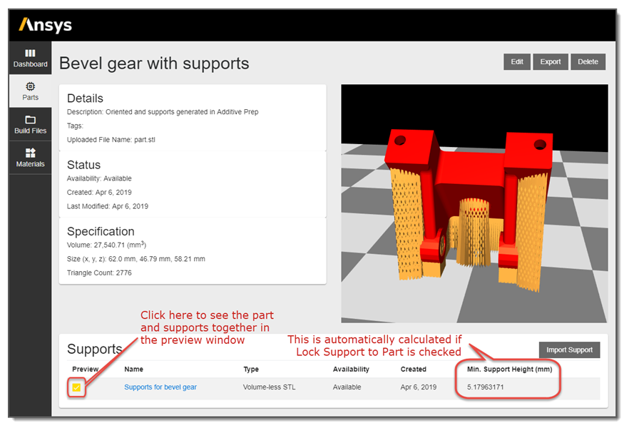
When this check box is checked, the Minimum Support Height input is disabled since that value will be calculated automatically.
Minimum Support Height (mm)
Enter a Minimum Support Height when Lock Support to Part is unchecked. This is the height, in millimeters, that the part will be elevated off the baseplate when the support is properly positioned below the part and the support is resting on the baseplate. In other words, the Minimum Support Height is the distance between the baseplate and the lowest point on the part when it is properly aligned with a given support. A value of 0 means that some point of the part will start printing directly on the baseplate.
It is important to be sure the supports and the part are properly aligned in the X and Y axes before importing. The correct Minimum Support Height ensures that the part and support are properly aligned in the Z axis at simulation time.
Known Limitation: When Supports Penetrate the Baseplate
The bounding box defining the simulation domain is expanded to account for the supports upon import, and the origin of the domain is translated to the minimum X, Y, and Z location of the expanded domain. The application assumes the X-Y plane at Z=0 of this translated origin is the top of the baseplate. This is based on the assumption that the part and support are always built on top of the baseplate.
A known limitation occurs when a support is designed with the intent of penetrating into the baseplate, where a small portion of the support is below the baseplate top surface. (Usually this is set by intrusion or penetration settings in support generation tools.) In these situations, the support will still be translated to the baseplate top surface, which can cause unexpected behavior in the simulation results, such as the part or other support structure being disconnected from the baseplate. You may recognize this by seeing unexpected gaps or unexpected result trends in some cases, but in other cases, where only some elements are affected, this could be difficult to observe.
In general, the known limitation exists where a part and/or support are designed with a lowest point being something other than Z=0. In the Additive application, because of the automatic translation defining the domain, they are treated as if the lowest point is at Z=0. The workaround is to not add bottom intrusion to supports, or to trim the bottom intrusion portion when preparing for simulation.
Support STL Type
Choose the type of support you are importing:
Volumeless STL: These supports are usually single-bead width support walls such as lattice supports. These structures do not need to be "watertight." Other names for this type include thin wall, vector, and facet.
Solid STL: These supports are standard, watertight geometry bodies. Other names for this type include thick wall, bulk, and volume.
Part and Support Preview
Click Save to initiate the import of the support. As is the case for importing the part, the status shows "Processing" while the support is being imported, and "Available" when the support has been fully processed. Once the support is Available, click the Preview check box to see the part and support together in the preview window.
To import another support for the same part, simply click Import Support again and go through the same process to import the new file. Use the Preview check box for each support to confirm its location with respect to the part. Note that you can preview only one support at a time using the Preview check box.
Support Groups
To use multiple supports .stl files in a single simulation, you must first create a support group. You can mix support .stl types, that is, volumeless supports and solid supports, in a support group. There is no limit to the number of supports a support group can contain, but supports can be in the same group only under these conditions:
The Minimum Support Heights are the same, or
The Minimum Support Height is zero and the support is locked to the part.