


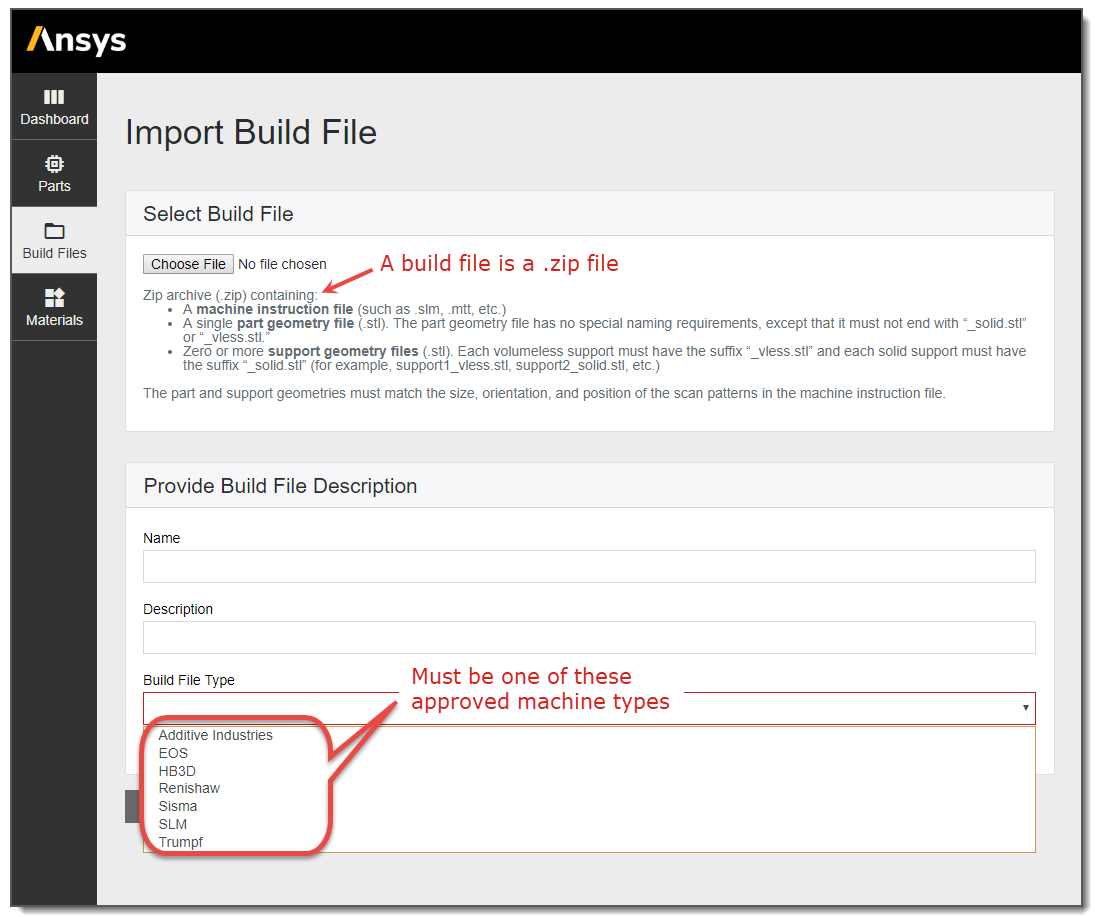
In the Additive Print application, we define a build file as a .zip file containing, at a minimum: one .stl file for the part geometry and one machine-specific print file defining the scan vectors. Supported machine manufacturers include Additive Industries, EOS, HB3D, Renishaw, Sisma, SLM, and Trumpf. Ansys may add additional options as we continue to work with more machine partners.
Machine-specific requirements are documented in the following sections but here are the general requirements for build files:
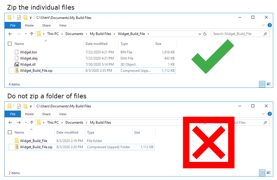
The build file is a .zip file. Do not nest the files to be zipped within a folder, as a folder structure is not readable. Rather, zip the individual files together as shown in the following figure.
Only one part can be included in a build file.
The baseplate should not be included in the part geometry file.
One or more supports may be included as separate .stl files. Support file names are required to have a suffix indicating their support .stl type, either volumeless ("*_vless.stl") or solid ("*_solid.stl"); for example, supports _at_holes_vless.stl, supports_at_overhang_vless.stl, supports_at_arch_solid.stl, etc. All the supports included in the build file will be used in your simulation if you choose to use the build file supports.
For the machine-specific print file:
One laser head is assumed for the simulation. Multi-laser build files are not supported. If you import a build file that includes multiple lasers, how it is handled in the application is machine-specific. In most cases the application either produces an error on import or ignores the extra lasers.
One set of process parameters is used in the simulation. If multiple parameter sets are included in the build file, say different scan speeds and laser powers for the part hatches versus the support hatches, the part hatch parameters will override. When running thermal simulations, parameters under Machine Configuration in the simulation form override.
Only one part layer thickness is allowed.
Only one support layer thickness is allowed, and it must be equal to, or a multiple of, the part layer thickness.
The scan sequence is always simulated from the inside out, that is, from hatch to contour scans, regardless of how they are defined in the build file. The appropriate order is maintained within the hatch area and within a contour, however. For example, if the build file order is: contour line 1 → contour line 2 → hatch line 1 → hatch line 2, it will be changed to be hatch line 1 → hatch line 2 → contour line 1 → contour line 2.
Scan vectors marked as contour will not be simulated in simulations that perform a full thermal solution (Thermal Strain and Thermal History simulation types). The definition of contour/hatch is established by the software that creates the build file. If contour-like scan vectors are marked as hatch they will be simulated and results may not be as expected.
Build files from Additive Prep are automatically created with a file name of "ansys_additive_print.zip.
To import a .zip file to the Build Files Library, click the Build
Files button  in
the left panel of the dashboard and then click Import Build
File. Click Choose File and navigate to the
appropriate .zip file on your computer. Provide a Name and
Description (optional) and then click Build File Type to choose which of the following approved machine type translators
Additive will use when reading the data:
in
the left panel of the dashboard and then click Import Build
File. Click Choose File and navigate to the
appropriate .zip file on your computer. Provide a Name and
Description (optional) and then click Build File Type to choose which of the following approved machine type translators
Additive will use when reading the data:
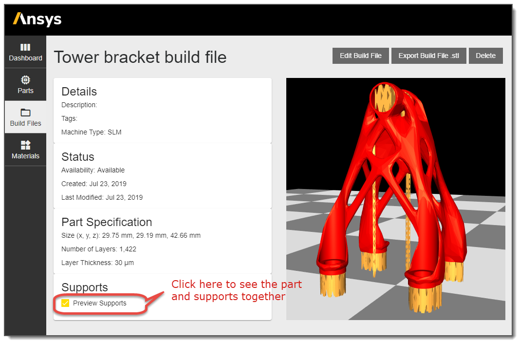
Once you click Save, you will see a message "Valid file selected. Build file importing now..." The import process may take several minutes, depending on the size of the file. During processing, a preview window appears with "Availability: Processing" status. The geometry is ready for simulation when you see the "Availability: Available" status.
If your build file includes supports, click the Preview Supports button to show the part and the supports together in the preview window.
Note: A build file may contain scan vectors that exceed the part geometry boundaries. Because the Mechanics Solver uses voxels based upon the part geometry, strains resulting from the portion of scan lines exceeding part boundaries may not be included in the stress calculation. This depends upon the amount by which scan vectors extend beyond the part boundaries. See the discussion of Voxel Sample Rate.