Your options for machine parameters in a Thermal Strain simulation depend on whether you have chosen a part file (does not include scan pattern information) or a build file (does include scan pattern information) in the Geometry Selection area of the simulation form.
If You Have Chosen a Part (in Geometry Selection)
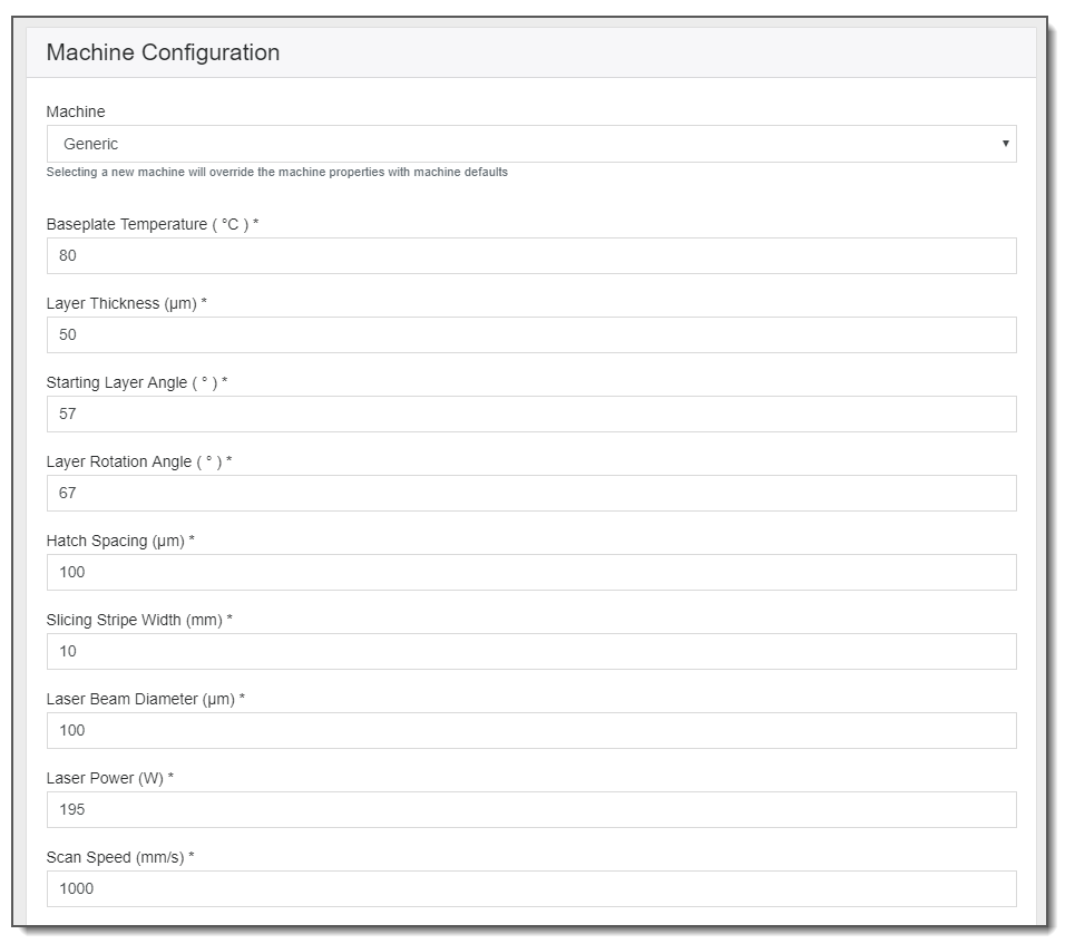
Without a build file, a Thermal Strain simulation assumes a rotating stripe scan pattern. As such, machine parameters required to establish the scan pattern include Layer Thickness, Starting Layer Angle, and Layer Rotation Angle. Additional machine parameters required are Baseplate Temperature, Hatch Spacing, Slicing Stripe Width, Laser Beam Diameter, Laser Power, and Scan Speed. See Understanding Machine Parameters. All of these machine parameters affect the temperatures at the nodes throughout the simulation.
If You Have Chosen a Build File (in Geometry Selection)
Currently, a Thermal Strain simulation supports build files with rotating stripe, checkerboard, and any other scan patterns, with or without contours. However, the scan vectors marked as contour will not be simulated. The definition of contour/hatch is established by the software that creates the build file. If contour-like scan vectors are marked as hatch they will be simulated and results may not be as expected.
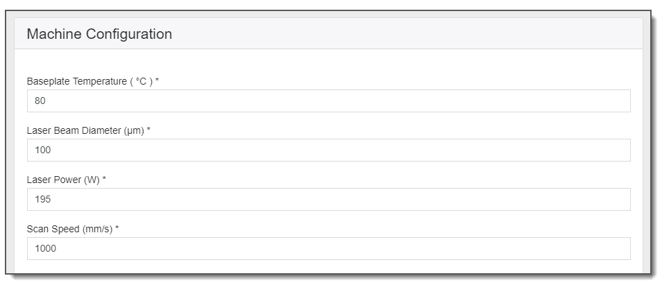
Important: The values of Baseplate Temperature, Laser Beam Diameter, Laser Power, and Scan Speed in the simulation form override the build file, so take care to set these parameters the way you want them.