Your options for machine parameters in a Scan Pattern simulation depend on whether you have chosen a part file (does not include scan pattern information) or a build file (does include scan pattern information) in the Geometry Selection area of the simulation form.
If You Have Chosen a Part (in Geometry Selection)
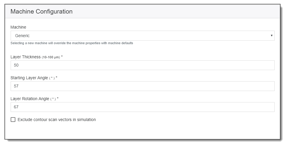
Without a build file, the Additive application uses an internal slicing function (called the slicer) and assumes a rotating stripe scan pattern with contours. As such, machine parameters required to establish the scan pattern include Layer Thickness, Starting Layer Angle, and Layer Rotation Angle. See Understanding Machine Parameters. You may exclude the contour scans in the simulation by clicking on the Exclude check box.
Note: For parts with a gap in the Z dimension in which there should be no scans at all, the slicer does add scans to those layers by taking the information from the last layer just before the gap. This is not a common situation but it is possible (for example, when there are multiple parts on the baseplate combined into one single .stl file). When this type of geometry is used in a simulation that uses the generic machine to create the scan pattern (i.e., the slicer), those empty layers will be filled with scan pattern generated using the information from the previous non-empty layer. If the previous non-empty layer happens to be just a point, then all the following gap layers will be empty as well. This can potentially cause problems such as incorrect simulation results. This limitation applies to any geometry in which its sliced layers have no contour and end up empty.
If You Have Chosen a Build File (in Geometry Selection)
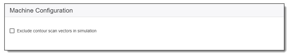
Currently, a Scan Pattern simulation supports build files with rotating stripe, checkerboard, and any other scan patterns, with or without contours. The machine parameters will be obtained from the build file. Your only option is whether to exclude contour scan vectors in the simulation.