


There are several standard machine parameters, also known as process parameters, used in Additive simulations. Each simulation (except the Assumed Strain simulation) uses some, or all, of these parameters. The machine parameters are shown in the following figure and are listed here for your reference.
When entering values for process parameters in the application interface, you may see a recommended range message. Values in a recommended range represent the values that Ansys has validated.
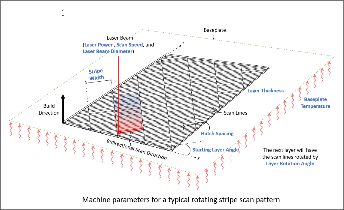
Laser Power (W)
The power setting for the laser in the machine. Must be between 50 and 700 Watts. Defaults to 195 Watts.
Scan Speed (mm/sec)
The speed at which the laser spot moves across the powder bed along a scan vector to melt material, excluding jump speeds and ramp up and down speeds. Must be between 350 and 2500 mm/sec. Defaults to 1000 mm/sec.
Laser Beam Diameter (µm)
The width of the laser on the powder or substrate surface defined using the D4σ beam diameter definition. Usually this value is provided by the machine manufacturer. Sometimes called laser spot diameter. Must be between 20 and 140 µm. Defaults to 100 µm.
Starting Layer Angle (°)
The orientation of fill rasters on the first layer of the part. This is measured from the X axis, such that 0 degrees results in scan lines parallel to the X axis. The starting layer angle is commonly set to 57 degrees. Must be between 0 and 180°. Defaults to 57°.
Layer Rotation Angle (°)
The angle at which the major scan vector orientation changes from layer to layer. This is commonly 67 degrees. Must be between 0 and 180°. Defaults to 67°.
Layer Thickness (µm)
The thickness of the powder layer coating that is applied with every pass of the recoater blade. We recommend that you use the actual thickness used for your machine and build material. Must be between 10 and 100 microns. Defaults to 50 microns.
Hatch Spacing (µm)
The distance between adjacent scan vectors when rastering back and forth with the laser. Hatch spacing should allow for a slight overlap of scan vector tracks such that some of the material re-melts to ensure full coverage of solid material. Must be between 10 and 1000 microns. Defaults to 100 microns.
Slicing Stripe Width (mm)
When using the stripe pattern for scan strategy, the geometry can be broken up into sections, called stripes. The stripes are scanned sequentially to break up what would otherwise be very long continuous scan vectors. Slicing Stripe Width is commonly set to 10 mm wide. Memory requirements for the thermal solution will expand significantly as you increase the Slicing Stripe Width much beyond the default. Must be between 1 and 100 mm. Defaults to 10 mm.
Baseplate Temperature ( °C )
The controlled temperature of the baseplate. Must be a real number between 20 and 500. Defaults to 80 °C.
Machine
A placeholder for future machine configurations. Defaults to Generic for now.