


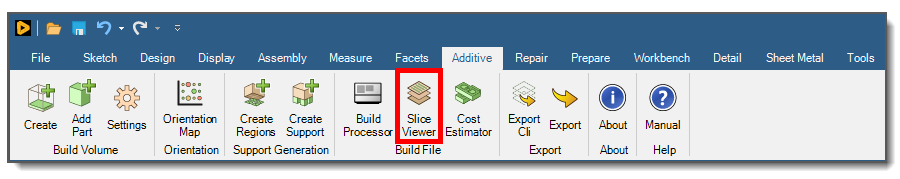
After generating the build file, you can use the Slice Viewer tool to examine the individual slices of your part, or the sequence of slices within the build. Click Slice Viewer in the ribbon to bring up the tool. It may take several minutes to load all the layers from the build file. Depending on your machine and model size, it could take up to an hour.
2D View
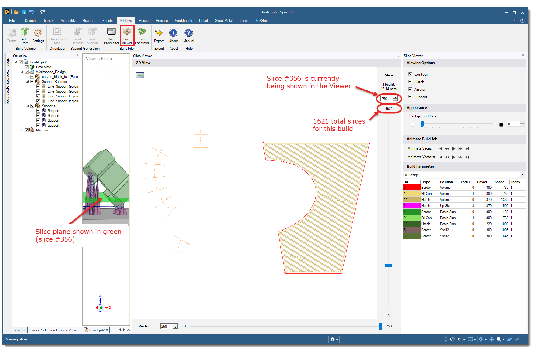
The Slice Viewer provides a two-dimensional view of any given individual slice in your part. In the 2D View window, move the Slice slider to view a particular slice in the 2D View window. This slider can be adjusted from 1 to the total number of slices in your part. Move the Vector slider to view the progression of the laser scan vectors in the direction in which they are created within that particular slice. This slider can be adjusted from 0 to the total number of vectors in the slice.
Viewing Slices
In the Viewing Slices area of the window, the green horizontal plane represents the current slice being displayed in the Slice Viewer. Notice how the green slice plane moves up and down as you slide the Slice slider up and down. Use your mouse, as needed, to orient the part in the Viewing Slices area for best viewing of the green plane. Note that moving the part in this way does not affect the 2D slice view.
Viewing Options
There are a number of options and features shown in the panel to the right of the 2D View. Not all build files have the same options in the panel, depending on the machine type. For example, EOS build files have fewer items shown because the information is not written by the API when creating the build file. The remainder of the discussion about the Slice Viewer describes options specifically for SLM machines.
Here you can control what is shown in the Slice Viewer and get scan pattern summary information.
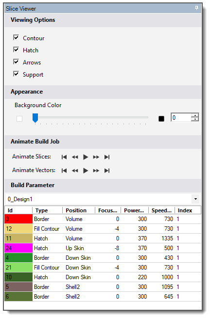
There are several viewing options to control how the slices are displayed. Use the check boxes to toggle on or off the following items:
Contour - The border vectors (red arrows)
Hatch - The bulk, or fill, vectors
Arrows - The vector arrows
Support - The support vectors (orange arrows)
Appearance
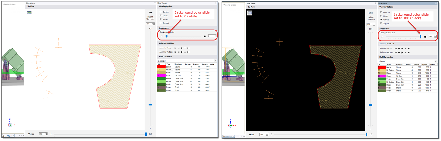
The background color in the 2D View window can be adjusted from white to black for more contrast using the slider.
Animate Build Job
There are two slice animation options:
Animate Slices – Animates the build process slice-by-slice. The Slice slider begins from its current position until it reaches the number of slices in the part, moving in the positive Z direction. The animation can be paused, sped up, and slowed down using the appropriate buttons.
Animate Vectors – Animates the current slice’s scan vectors. The Vector slider begins from zero until it reaches the total number of vectors in the slice, moving in the positive X direction. The animation can be paused, sped up, and slowed down using the appropriate buttons.
Build Parameters
Here you can see the most important build parameters, namely power and speed, for each type of scan vector in the build file. For example, in the Slice Viewer dialog above, the hatch - volume scans will be exposed with a laser power of 370 Watts and a scan speed of 1335 mm/sec. Remember that power and speed settings are built into the build strategy that you choose but may be changed in the Build Processor, under Scanning Parameters.