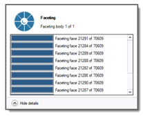
Before you can orient the part, you must select the Workspace (or any of the components in the workspace assembly) to use the orientation maps. Click Orientation Map to bring up the orientation map panel. The calculations begin immediately. It may take several minutes for the orientation maps to populate initially, depending on the complexity of your part. If your part is in .stl format already, the Additive Prep application will use those facets to perform its operations. If your part is in SpaceClaim's .scdoc format, or any non-faceted format, the application will first convert it to facets. You may see a status window showing the progress of the faceting operation as shown here.
The following steps reflect the typical sequence for orienting a part but you may perform them in any order.
Drag the slider, or use the numeric input field, to set the Z-Offset (the distance between the lowest point of the part and the baseplate). When you rotate your part in the Combined Current Settings orientation map, the position of the part will automatically be adjusted to maintain the Z-Offset value.
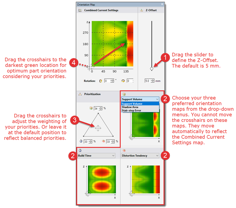
If the three orientation maps shown do not reflect your priorities, select other orientation map options from the drop-down menus. See the section "Orientation Map Options" for more information on available options.
Drag the crosshairs in the prioritization triangle, or use the numeric input fields, to adjust the weighting of priority among the three orientation maps. The higher the number for a given factor, the more weight that factor will be given when calculating the optimum part orientation. For example, if build time is most important to you, move the crosshairs closer to the vertex of the prioritization triangle that is marked with a stopwatch. The composition of the Combined Current Settings orientation map will dynamically adjust to reflect your priorities as you move the crosshairs around in the triangle.
Drag the crosshairs, or use the numeric input fields, in the Combined Current Settings orientation map to orient the part. You may want to drag the crosshairs to the darkest green position in the map as this represents the optimum positioning given your priorities. There may be several locations on the map with the same dark green color. This means that several orientations are considered optimal. While you are moving the crosshairs around in the map, you will see the part dynamically rotating in the design window.
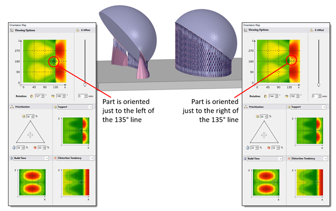
Often in an orientation map you will see a distinct, straight line of color change. This is usually a demarcation pertaining to the Overhang Angle. In this example, two identical half sphere parts with slightly different orientations are shown in the figure. The Overhang Angle is 45°. One part (on the left) is oriented in the near optimum zone to the left of the X=135° line and very few supports are required to hold the part. The other part (on the right) is oriented just past X=135° which is into the zone not recommended for volume of supports. As you can see, there are many more supports required to hold the part to the baseplate.
Have some fun and play around with the orientation map controls! See the effect of changing the weightings in the prioritization triangle. Explore different part orientations. Try to get an intuitive feel for how the part rotates by dragging the crosshairs along different axis lines in the Combined Current Settings orientation map.
Note: The orientation maps are calculated dynamically. As such, the maps themselves are not saved to an .scdoc file and must be calculated again if you close out of SpaceClaim and then reopen the application. Of course the orientation of your part is saved on the .scdoc file and that is the important thing.
Orienting a Part — Guidelines and Troubleshooting
Long time to calculate orientation maps
If it is taking a long time to calculate the orientation maps, you can still orient the part and continue your workflow without the maps. Alternatively, to speed up orientation if you have a large, complex model, you can lower the tessellation resolution to "low" in Additive Prep options. Tessellation resolution has an impact on orientation map generation. But you will want to reset the resolution before generating supports. You will need to restart each time you change options.
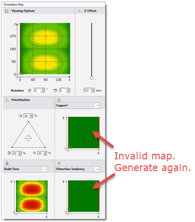
An all-green orientation map
On rare occasions, you may see an all-green map for one or more of the orientation maps. This indicates an invalid map that is just a temporary condition. Simply close the orientation map panel (by clicking the Orientation Map button in the ribbon) and then open it again.