


Orient parts in the build chamber using orientation maps. Choose the three priorities that are most relevant to you, weight those three priorities to produce a composite map from your settings, then orient the part according to the combined settings.
Five orientation maps are available:
Build Time
Support Volume
Distortion Tendency
Shadow Area
Stair-step Error
Several heat maps are shown in the orientation map panel. The maps use different colors to display the effect of different orientation options. The colors indicate whether the orientation of the part is good or in need of optimization. Green indicates optimum orientation. Red indicates an orientation that is not recommended. The larger orientation map at the top of the panel (Combined Current Settings) shows the values of the three options you have chosen, combined according to the prioritization weightings you choose.
The horizontal axis of any orientation map shows the rotation of the part around the X-axis from 0° to 180°. The vertical axis shows rotation of the part around the Z-axis from 0° to 360°. All possible orientations of the part are possible using these two axes of rotation together.
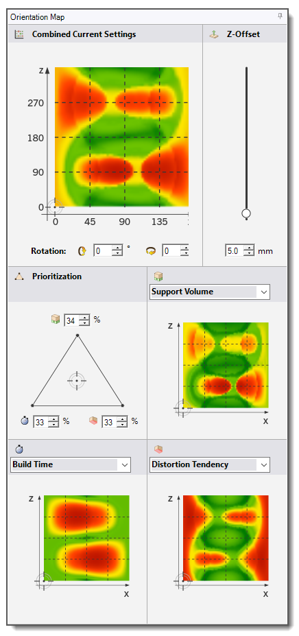
Combined Current Settings Orientation Map
An overall orientation map reflecting the combined current prioritization weightings you establish in the weighting triangle for the three orientation options you select. If, for example, the weighting is completely based on build time, the Combined Current Settings and Build Time orientation maps match. By default, the Combined Current Settings orientation map is set to reflect relatively even weighting from all three selected priorities, that is, 33% priority for the first option, 34% for the second option, and 33% for the third option.
The current orientation of the part is marked by the crosshairs on this orientation map. To change the orientation of the part, click in the map, drag the crosshairs to a new location on the map, or change the numerical Rotation settings below the map.
Z-Offset
Z-Offset is the distance (in millimeters) from the current lowest point of the part to the baseplate. The default Z-Offset is set to 5 mm. If you modify the rotation settings of the part so that the distance between the baseplate and the part changes, the location of the part is moved to maintain this offset.
Prioritization Triangle
Use the triangular weighting tool used to assign priorities to the three options you select. This tool adjusts the overall Combined Current Settings orientation map. Weights are distributed depending on the position of the crosshairs in the triangle. You can drag the crosshairs or change the numerical settings to modify the weighting. By default, the triangle is balanced to reflect even weighting for all three priorities, that is, roughly one third (32% to 34%) for each.
Orientation Map Options
Five orientation maps are available, but only three may be selected. Choose an option from the drop-down menu for each orientation map. Each option has a unique icon that represents that option on the prioritization triangle. You cannot choose the same option for more than one orientation map. If you are only concerned with one or two options, modify the prioritization triangle to de-emphasize the orientation map or maps that are of less concern to you.
- Build Time
A color-coded map of part orientation around the X and Z-axes based on the relative amount of time it will take to build the part in that orientation. Green areas on the map indicate orientations that will build faster. Red areas denote orientations that will take more time to build..
- Supports
A color-coded map of part orientation around the X and Z-axes based on the relative amount of supports needed to build the part in that orientation. Green areas on the map denote orientations that require fewer supports. Red areas denote orientations that require a greater volume of supports.
The calculation is based on the total volume to be supported. The Overhang Angle is used to determine the surfaces to be supported and then supports are projected to the baseplate creating a total support volume. The Overhang Angle is set in the Settings option under Build Volume in the UI ribbon. By default, Overhang Angle is 40°.
- Distortion Tendency
A color-coded map of part orientation around the X and Z-axes based on potential distortion of the part if built in that orientation. Distortion tendency is not calculated based on a simulation but on a simplified, proprietary calculation that approximates potential for distortion. Green areas on the map denote orientations that will have less distortion tendency. Red areas denote orientations that will have a greater tendency for distortion.
- Stair-step Error
A color-coded map of part orientation around the X and Z-axes based on the relative overall amount of stair-step error in the part if built in that orientation. Additive manufacturing introduces stair-step error caused by the slicing of the component into layers, as indicated in the following figure. The error is 0 for surfaces with 0° and 90° to the build direction. The error is highest for surfaces at an angle of 45°.
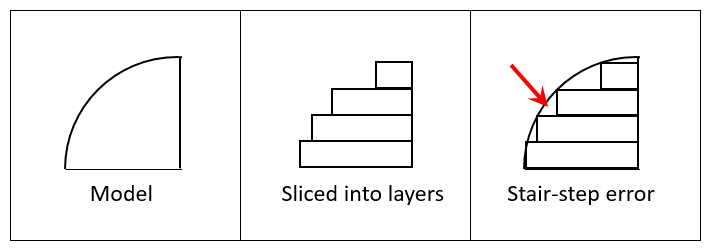
Green areas on the orientation map indicate orientations that will result in less overall stair-step error. Red areas on the orientation map indicate orientations that will result in more overall stair-step error.
- Shadow area
A color-coded map of part orientation around the X and Z-axes based on the relative overall build plate area that will be occupied by the part if built in that orientation. When trying to fill a platform with a maximum number of individual parts, you may wish to orient each part so that it blocks a minimal area on the build plate. Green areas on the map denote orientations that require less build plate area. Red areas on the map denote orientations that require more area on the build plate.