


Typically, you’ll have these geometric bodies in the simulation model:
Part – This is the part you are manufacturing. It should be a closed volume (that is, watertight), and should be oriented with the global X, Y, or Z axis as the print direction. The part can be made of multiple bodies but they must have shared topology between them.
Base Plate – This is the platform on which the part is to be printed. It is included in the simulation because it acts as a heat sink.
For your part geometry, commonly imported file types include SpaceClaim .scdoc files (non-faceted) and stereolithography .stl files (faceted). For other options, see Attach Geometry/Mesh in the Mechanical User's Guide.
Note that supports are not used in a typical DED process because the multiple axis turntables rotate the build platform to facilitate material deposition. This is unlike in a powder bed fusion process where supports are used to anchor the part to the base plate and supports must therefore be included in the simulation.
Procedural Steps
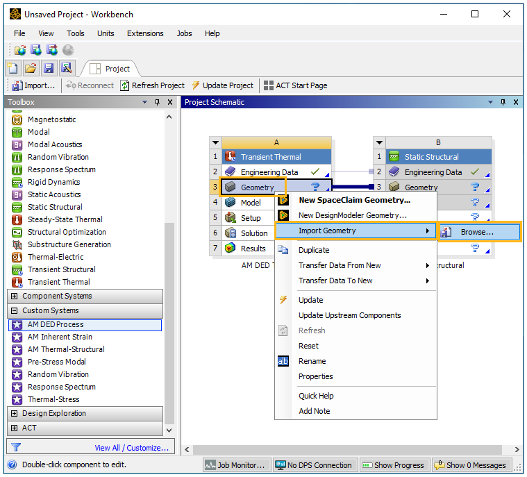
Right-click the Geometry cell of the Geometry block, and select Import. Browse for your file and import it. (Double-clicking the Geometry cell opens SpaceClaim.)
After importing geometry, double-click the Model cell (or right-click, and select Edit) of the Transient Thermal analysis block to launch the Mechanical application. It may take a few minutes for Mechanical to open and your geometry to appear in the geometry window.
Once your geometry is loaded in Mechanical, review how it is presented in the project tree.
Once the Mechanical application opens, it is a good time to adjust the number of processors (cores) you are using on your computer. Depending on the complexity of your model, DED process simulations may be computer intensive. If you have an Ansys HPC license, access the option in the Solve group on the Home tab and change the Cores to something appropriate for your simulation.