The following extrusion types are available:
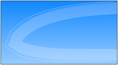
Wire Frame: This type can be used to investigate the lay-up of shell elements. The mid-surface of the plies are represented by lines, as shown below.
Surface Section Cut: For this type, the plies are shown as surface elements. A surface Section Cut generates a continuous mesh w can be used for 2D analyses. Therefore, Drop-Off elements are generated by default at the ply boundaries (like the solid model extrusion). If this does not represent the real structural behavior, then you can use the Butt Joint Sequence to control the connectivity of the adjacent plies and Drop-Off behavior. The surface Section Cut supports two types of extrusion:
: The extrusion follows the element normals of the reference surface. The offset direction does not change during the extrusion.
: The offset direction follows the interpolated element normals (potential field defined by the shell normals). The interpolation is based on a Look-Up Table that specifies the Search Radius and Number of Interpolation Points.
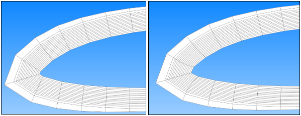
In general, the sweep-based algorithm is more robust in sharp corners with thick laminates; however, the extrusion of t-joints may be less accurate. The sharp corner in Figure 2.99 illustrates the difference between the extrusion algorithms.
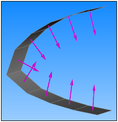
Surface Normal: The plies are illustrated by surface elements. The extrusion follows the element normals.
Surface Sweep Based: The plies are shown as surface elements. The offset direction follows the interpolated element normals (potential field defined by the shell normals).
The interpolation is based on a Look-Up Table which specifies the Search Radius and Number of Interpolation Points.
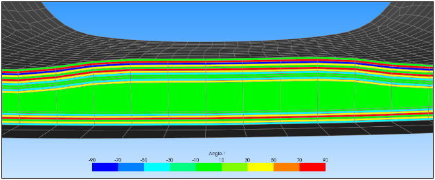
Section Cuts can also be used to plot ply-wise properties such as angles. For more information, see Lay-Up Plots.