Rosettes are coordinate systems used to set the Reference Direction of Oriented Selection Sets. Rosettes define the 0° direction for the composite lay-up. Coordinate systems defined in Mechanical are imported by default and the naming is maintained between Mechanical and ACP. Additional Rosettes can be defined in ACP. There are 5 different types of Rosettes. The origin and directions of Rosettes are given in the global coordinate system. Rosettes are independent of the mesh, even if you select nodes and elements to define their properties.
One or more Rosettes can be used to set the Reference Direction for elements in an Oriented Selected Set (OSS). The Selection Method in the OSS definition controls which Rosette determines the Reference Direction for the elements. The Reference Direction for a single element is determined by a projection of the applicable Rosette onto the element. Different Rosette types can be used to define the Reference Direction.
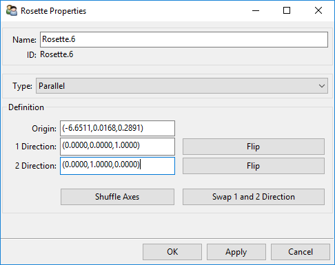
Flip Buttons: Reverse the direction
Shuffle Axes: Rotate coordinate system to exchange the X, Y, and Z axis.
Swap 1 and 2 Direction: Exchange direction 1 with 2.
Rosette Types
Parallel: Analogous to a Cartesian coordinate system. The Reference Direction is given by the Rosette's X direction.
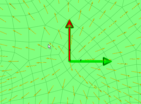
Radial: the Reference Direction for a radial Rosette is perpendicular to the Z direction. The Z direction lies orthogonal to Direction 1 and Direction 2 in the Rosette properties. The Reference Direction for an individual element is defined by the vector of Rosette origin to element center which is projected onto the element. If the direction vector cannot be projected the alternate Direction 1 is chosen.
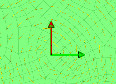
Cylindrical: Based on a cylindrical coordinate system. The Reference Direction runs circumferentially around the Rosette's Z direction according to the right hand rule. The Z direction is defined by the X and Y direction vectors. Flip the Z direction to reverse the Reference Direction.
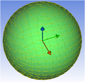
Spherical: Based on a spherical coordinate system. The Reference Direction runs circumferentially around the Z axis of the Rosette.
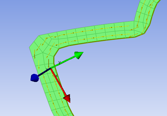
Edge Wise: Requires the selection of an Edge Set in addition to the usual Rosette definition. The Reference Direction is given by a projection of the Rosette's X direction and the path of the Edge Set. The X direction of the Rosette coordinate system is projected on to the point on the Edge that is closest to the origin of the Rosette. This determines Reference Direction along the Edge Set. The Reference Direction is reversed by switching the coordinates of the Rosette's X direction. An element within an Oriented Selection Set gets its Reference Direction from the direction of the point on the edge that is closest to the element centroid.