Creating a Solid Model
You can generate a Solid Model by performing a mesh extrusion which converts the shell-based lay-up definition into a layered, solid-element mesh. The configuration of the extrusion happens in ACP (Pre) with the Solid Model feature. (For details, see Solid Models in the Usage Reference chapter.) The options and advanced settings of the Solid Model feature control the extrusion, shape, and mesh quality. See Guide to Solid Modeling for practical tips and recommendations.
The Export settings for the Sold Model control how it is exported for downstream analysis. For instance, you can choose between different element types (layered solid185 or solsh190). Within Workbench, the element and node labels are automatically handled to avoid numbering conflicts. (See the section on Assembly.) If automatic numbering is disabled, then the numbering options can be used to specify the initial labels.
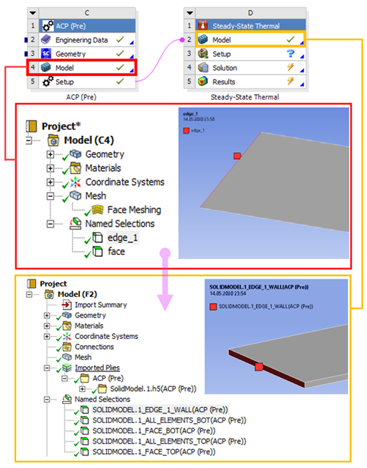
In addition, Element Sets and Edge Sets are transferred from ACP (Pre) to the downstream analysis system (Mechanical Model) where they appear as Named Selections. This aids the definition of boundary conditions and contacts, for instance, and makes your model associative. (See the section on Solid Model Properties for more information.) The figure below shows how Named Selections of the shell geometry are converted into Named Selections of the solid mesh (geometry). An edge becomes a wall (edge_1 ⇒ EDGE_1_WALL) and a surface is converted into a bottom and top surface (face ⇒ FACE_BOT and FACE_TOP) in the solid of the downstream Mechanical system.