


Within Ansys Workbench, there are two ways to analyze composite solid models: The analysis can be done in Workbench Mechanical, or it can be carried out in Mechanical APDL (Ansys Classic). While the functionality is identical, the user interface is very different. As an alternative, composite solid models can be exported from ACP for processing outside of Ansys.
Analysis with Mechanical
The composite layered solid element model appears in Mechanical as a meshed body. Any other bodies in the ACP (Pre) component are not carried forward. The user can define loads, boundary conditions, and connections to other parts in the usual Mechanical fashion. An example of such a solid model workflow is shown below:
Analysis with Mechanical APDL
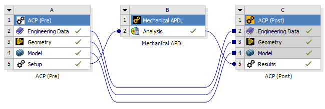
A further option is to link solid models to a Mechanical APDL where the boundary conditions and loads are defined. Typically, an APDL script is used to set boundary conditions and analysis settings for a workflow with Mechanical APDL. An example of a solid model workflow with Mechanical APDL is shown below:
Adding an ACP (Pre) Component to the Project
The solid modeling workflow in Ansys allows the assembly of many pre-processing components into one analysis system. In some cases, it may be desirable to analyze thick-walled composites in isolation but often it is desirable to see the interaction between multiple bodies. The connection procedure is explained with the help of two examples for both analysis methods (Workbench Mechanical and Mechanical APDL).
Link with Workbench Mechanical
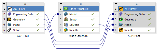
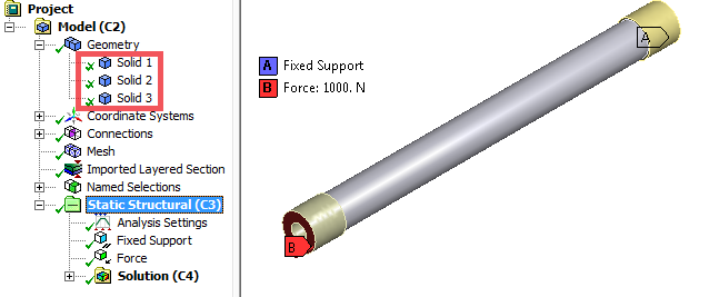
The procedure for building an analysis model is illustrated with a Static Structural Analysis system as an example. A composite tube connected to two metal inserts is subjected to torsion. A Project Schematic is shown below:
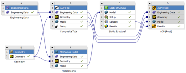
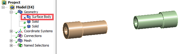
In this example, the geometry consists of one shell and two metal inserts. The link between ACP (Pre) (B5) and the Static Structural (C2) only transfers the generated layered solid element model. The link between the Mechanical Model (F4) and the Static Structural (C2) transfers all active bodies. As such, the shell geometry has to be suppressed. Consequently, all three parts appear as solid bodies in the Static Structural (C2) component. The connections, boundary conditions and all other pre-processing definitions can be defined in the Setup (C3) in the usual fashion. The global solution can be determined and analyzed in Workbench Mechanical while the composite component can be analyzed in detail in ACP (Post) (D5).
Link with Mechanical APDL
Two composite components serve as an example for the Mechanical APDL workflow procedure - a plate and a t-joint. A Project Schematic is shown here:

The proper sequence of connecting the system always begins with connecting an ACP (Pre) component first. In this case, it is not important because both inputs are ACP (Pre) solid models.
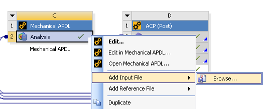
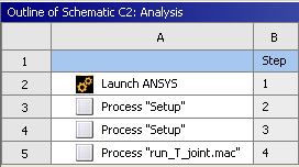
In the Mechanical APDL component the boundary conditions, loads and all other pre-processing definitions can be defined through APDL macros. These macros can be linked with the Mechanical APDL cell which will be integrated in the automatic update functionality of Workbench. A macro file can be added to the component through the right-click context menu (see figure below). Add Input File... appends the APDL running sequence with an additional macro. Check the order of the files of the Mechanical APDL component. The macros should be listed after the Solid Model Process Setup file(s).
Multiple Parts (Adding Other Systems)
It is possible to add multiple components to one analysis system: two composite parts or a composite part connected to two isotropic parts, for example.