


To launch Material Designer double-click the Material Designer cell of the Material Designer component system.
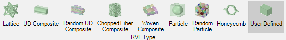
Click User Defined in the Ribbon Bar:
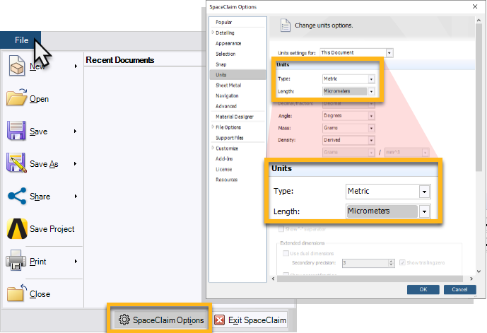
Check that the correct units are specified in Material Designer:
Select File in the Ribbon Bar
Select SpaceClaim Options
Select Units and check that Micrometers are used as length unit (Note that copying and pasting a SpaceClaim geometry for the RVE will not work unless micrometers units are used)
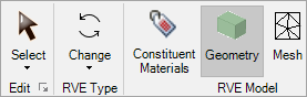
Select Geometry in the Material Designer ribbon bar:

Transfer the RVE geometry from SpaceClaim to Material Designer. To do so you can simply copy and paste the bodies from the SpaceClaim active window to the Material Designer active window.
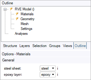
Select RVE Model () in the Outline panel and add two phases named
steel sheetandepoxy layer.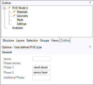
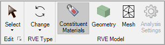
Select Constituent Materials in the Material Designer Ribbon Bar.
Assign the epoxy material to the epoxy layer and the steel material to the steel sheet .
Select Geometry in the Material Designer ribbon bar.
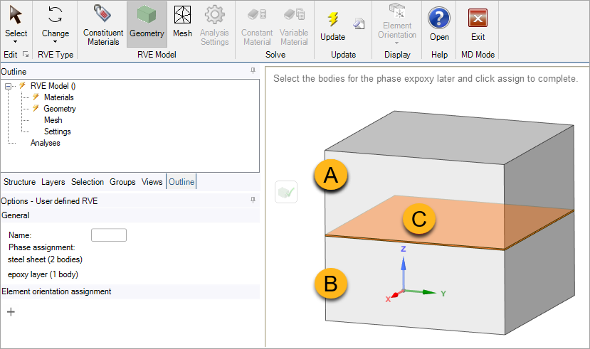
Assign the phases to the RVE bodies:
Select the phase named steel sheet. Then select the upper and lower bodies of the laminate (A and B in the image below). Confirm the assignment by clicking
 .
. As above, select the phase named epoxy layer, then select the middle body (C), and confirm the assignment
. 
Note: As all the constituent material properties are isotropic, you do not need to set coordinate systems explicitly. In a more general case, you would need to set them at this point. See User Defined RVE.