Analytical Models
This page lists and describes some of the analytical models available in Speos to represent and generate BSDF.
The analytical models are respectively defined as follows:
ABg
The ABg BSDF model can be used to describe scatter from smooth optical surfaces such as lens or mirror surfaces.
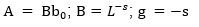
This model is defined as follows:
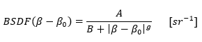
Where b=sinqscatter, b0=sinqspecular and A, B, g are the specific model parameters.
The ratio  corresponds to the maximum value of the BSDF in the specular direction. The quantity B1/g corresponds
to the angle at which the BSDF transitions from a constant value to power-law falloff. The slope g corresponds to the slope of the BSDF.
corresponds to the maximum value of the BSDF in the specular direction. The quantity B1/g corresponds
to the angle at which the BSDF transitions from a constant value to power-law falloff. The slope g corresponds to the slope of the BSDF.
The coefficients/parameters of the model are either guessed or estimated thanks to the RMS surface roughness and the total integrated scatter (TIS).
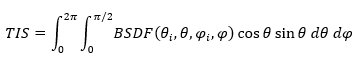
The total integrated scatter of a surface is given by the formula:
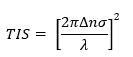
Where Dn is the refractive index difference across the surface (Dn = 2 for a mirror), s is the RMS surface roughness and l is the incident wavelength.
We can relate the TIS and the ABg model with the following relationship:
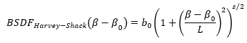
Harvey Shack
This model is similar to the ABg model. It states that the scatter behavior of smooth surfaces does not depend on the incident angle and it is defined as a linear-shift invariant function.
The equation is defined as follows:
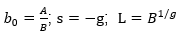
ABg and Harvey Shack Conversion
As an equivalence exists between both models, a conversion is possible.
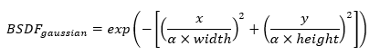
Gaussian, Elliptical and Rectangular models
These models allow to create diffusers that can be used for HUD systems.
Two different intensity profiles can be created with these models:
An intensity profile such as Gaussian BSDF.
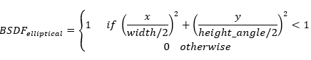
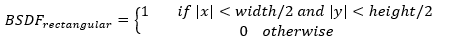
A geometrical profile like Elliptical or rectangular BSDF.
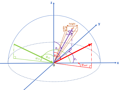
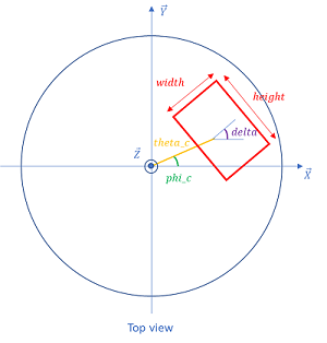
The orientation of the BSDF is driven by three angles expressed in radians: Two angles, theta and phi enable you to position the center of the BSDF and delta enables you to rotate the BSDF around its center.
The parameters of the model are illustrated in the following figure:
 |
 |
|
delta corresponds to the rotation of the surface around OC axis. theta c corresponds to the zenithal angle. phi c corresponds to the azimuthal angle. Theta c and Phi c are defining the positions of the center of the rectangle. |
|
The equations for each model are the following: