


Creating an Immersive Sensor
This page shows how to create an Immersive Sensor to visualize what is viewed from a specific point of view of a scene. An immersive sensor allows you to generate an .speos360 file that can be visualized in Virtual Reality Lab.
Important: This feature is only available under Speos Premium or
Enterprise license.
To create an Immersive Sensor:
-
From the Light Simulation tab, click VR
_Sensor_VR.png) > Immersive .
> Immersive .
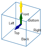
Spatial indicators appear in the 3D view to demonstrate how the sensor is oriented in space (front, back, bottom, top, left and right positions are indicated).
-
If you want to adjust the Axis system of the sensor:
_Sensor_Immersive_Axis_System.png)
- Click
_Origin_Point.png) to select another origin
than the absolute origin of the assembly.
to select another origin
than the absolute origin of the assembly. - Click
_Sensor_Front_Direction.png) and select a
line to define the Front direction (corresponding by default to Y
axis).
and select a
line to define the Front direction (corresponding by default to Y
axis). - Click
_Sensor_Top_Direction.png) and select a line
to define the Top direction (corresponding by default to Z axis).
and select a line
to define the Top direction (corresponding by default to Z axis). - or click
_Axis_System_Autofill.png) and select a coordinate
system to autofill the Axis System.
and select a coordinate
system to autofill the Axis System.
Important: Make sure the sensor is not tangent to a geometry.Note: Make sure no geometry intersects the sensor. Otherwise you may generate unexpected black result in CPU simulation.Note: If you define manually one axis only, the other axis is automatically (and randomly) calculated by Speos in the 3D view. However, the other axis in the Definition panel may not correspond to the axis in the 3D view. Please refer to the axis in the 3D view. - Click
-
In General, edit the Sampling value to recalculate
the Central resolution.
The Central resolution is automatically calculated and depends on the Sampling value.
_Sensor_Immersive_General.png)
-
In Wavelength, define the spectral excursion of the sensor:
_Sensor_Wavelength.png)
- Edit the Start (minimum wavelength) and End (maximum wavelength) values to determine the wavelength range to be considered by the sensor.
-
If needed, in Sampling, adjust the number of wavelengths to be computed during simulation.
The Resolution is automatically computed according to the sampling and wavelength start and end values.
Note: The sensor sampling is used for each face.Every wavelength beyond the defined borders are not taken into account by the sensor.
-
In Faces, define which faces to include/exclude.
_Sensor_Immersive_Faces.png)
-
In Optional or advanced settings
_Speos_Options.png) :
:
_Sensor_Immersive_Optional_Advanced_Settings.png)
- If needed, in Visualization size, adjust the preview of the sensor's size.
- In Preview, from the Active Vision Field
drop-down list, select which face of the sensor should be used as default viewpoint for the Automatic framing
_Sensor_Automatic_Framing.png) option.
option. _Sensor_Immersive_Active_Vision_Field.png)