


Physical Optics
The Physical Optics options are set in the Physical Optics section of the Surface Properties window. The Surface Properties can be reached by clicking the down arrow in the Surface Properties bar above the Lens Data Editor.
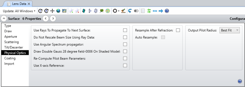
Use Rays To Propagate To Next Surface
If checked, then the diffraction propagation algorithms will not be used to propagate the beam to the next surface. Instead, rays will be traced to the next surface and the resulting ray transfer function will be used to propagate the beam and update the pilot beam parameters. Use of this feature is required for non-sequential, birefringent, and gradient index surfaces. Multiple sequential surfaces may all have this option checked, in which case the beam will advance through all the surfaces using only ray propagation. This feature may also be used to speed up the propagation algorithm by propagating through several surfaces at once, if the distance between the surfaces is small enough so that the diffraction propagation is unimportant. The default is unchecked. Search the help files for "Considerations when using rays to propagate" for important information about using this feature near surfaces where the rays come to a focus.
Do Not Rescale Beam Size Using Ray Data
By default, OpticStudio will use the ray grid to determine any distortion, stretching, scaling or other change in the beam shape. A good example of this is the passing of the beam through a grating. The beam will become compressed along the direction of the diffraction. However, there are times when this computation fails. One such case is when the ray grid enters a caustic. The rays no longer accurately represent the beam, and should not be used to determine the beam shape. OpticStudio automatically skips this step if it detects the ray grid is in a caustic, however, there may be other cases where the algorithm should not be applied, and this option allows user selective disabling of the algorithm.
Use Angular Spectrum Propagator
If selected, the angular spectrum propagator will be used for propagation through the surface instead of the propagator OpticStudio would automatically select. This option should only be used if the beam size does not change dramatically over the propagation distance. The array width will remain constant using the angular spectrum propagator. The default is unchecked.
Draw "lens file name-surface #" on shaded model
If selected, the ZBF of the displayed name will be drawn on shaded model layout plots at the location of the surface. The file name is the same as the name of the lens file, with a 4 digit suffix equal to the surface number. This is the same name convention that automatically saved beam files use. See "Display Tab" for information on saving beam files at every surface. If this option is selected, and the correct beam file name is found, then the surface itself will not be drawn, just the beam file at that surface. For this reason, this option works best on dummy surfaces. Drawing large beam files uses considerable amounts of memory and will slow down the drawing of shaded model displays.
Re-Compute Pilot Beam Parameters
Some surfaces significantly alter the beam characteristics. A good example is a pinhole aperture. After passing the aperture, the beam waist size, divergence, and position may be significantly altered, even though technically the pinhole has no optical power (this is in fact the core difference between geometric and physical optics). After passing the pinhole, the pilot beam parameters need to be recomputed for subsequent accurate propagation. Checking this option will invoke an algorithm which finds the pilot beam parameters that best fit the actual beam.
Use X-axis Reference
By default, the grid of rays used to generate the transfer function at any surface is oriented such that the Y-axis of the grid aligns with the Y-axis of the beam. In highly tilted systems this choice of alignment may not be appropriate. This option allows the orthogonal choice of grid alignment, i.e. one in which the X-axis of the grid aligns with the X-axis of the beam.
Resample After Refraction
This control allows the beam sampling and width to be changed after propagating through any surface. If selected, the new x and y sampling and beam width may be specified. Note that this control is ignored if rays are used to propagate through the surface. See also "Auto Resample" below.
Auto Resample
If checked, the beam will be automatically resampled. The algorithm used first recomputes the pilot beam parameters as described in "Re-Compute Pilot Beam Parameters" above. The X and Y- widths are then set according to the equations described in "Comments about point spacing and sampling". The number of points used in the X- and Y- sampling will not change.
Output Pilot Radius
The output pilot beam is used to reference the phase and other properties of the beam after refraction through the surface. This control defines the method of computation for the phase radius of curvature of the output pilot beam.
Best Fit selects the optimum pilot beam based upon ray tracing through the surface and is the recommended setting.
Shorter selects the shorter of the pilot X or Y phase radii.
Longer selects the longer of the pilot X or Y phase radii.
X and Y explicitly choose the pilot X or Y phase radii.
Plane selects a pilot beam with a waist at the surface and infinite phase radius.
User allows specification of the X and Y radius in lens units. Use the value of zero for infinite radius.
Next: