

Thermal Resistance [Output Data]
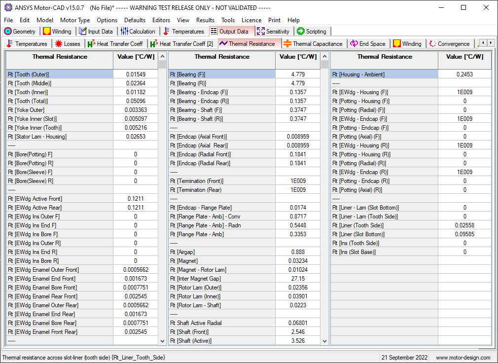
Set of 3 Grids showing numerical Output Data for the following thermal resistance parameters:
Rt [Tooth(Outer)] Thermal resistance outer half of stator tooth - radial direction. Labelled Tooth/2 in Schematic.
Rt [Tooth(Inner)] Thermal resistance inner half of stator tooth - radial direction. Labelled Tooth/2 in Schematic.
Rt [Yoke Outer] Thermal resistance outer half of stator yoke - radial direction. Labelled Yoke(Outer) in Schematic.
Rt [Yoke Inner (Slot)] Thermal resistance inner half of stator yoke above slot - radial direction. Labelled Yoke(Back Iron) in Schematic.
Rt [Yoke Inner (Tooth)] Thermal resistance inner half of stator yoke above tooth - radial direction. Labelled Yoke(Tth) in Schematic.
Rt [Stator Lam - Housing] Thermal resistance between stator lamination and housing (interface resistance). Labelled Lam-House in Schematic.
Rt [Housing - Radial] Thermal resistance of housing radial thickness.
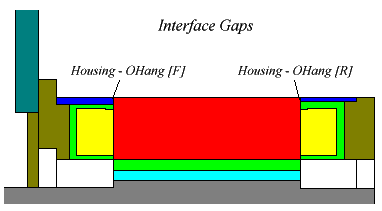
Rt [Housing - Housing OHang (R)]Thermal resistance between active section of motor and housing overhang [rear of motor]. Used to model frameless motors that have Housing Dia = Stator Lam Dia and -ve value of Housing Step [R]. Labelled H-Hoh[R] in Schematic.
Rt [Housing - Housing OHang (F)]Thermal resistance between active section of motor and housing overhang [front of motor]. Used to model frameless motors that have Housing Dia = Stator Lam Dia and -ve value of Housing Step [F]. Labelled H-Hoh[F] in Schematic.
Rt [Housing OHang/2 (R)] Thermal resistance of housing in axial direction along 1/2 overhang at rear of motor. Labelled Housing[R]/2 in Schematic.
Rt [Housing OHang/2 (F)] Thermal resistance of housing in axial direction along 1/2 overhang at front of motor. Labelled Housing[F]/2 in Schematic.
Rt [Liner - Lam (Slot Bottom)] Thermal resistance of gap between slot liner and stator lamination (bottom of slot). Labelled Liner-Lam in Schematic.
Rt [Liner - Lam (Tooth Side)] Thermal resistance of gap between slot liner and stator lamination (side of tooth). Labelled Liner-Lam in Schematic.
Rt [Liner (Slot Bottom)] Thermal resistance across slot-liner (bottom of slot). Labelled Liner in Schematic.
Rt [Liner (Tooth Side)] Thermal resistance across slot-liner (side of tooth). Labelled Liner in Schematic.
Rt [Housing - Endcap (F)] Thermal resistance between housing and endcap [Front of motor]. Labelled House-Ecap in Schematic.
Rt [Housing - Endcap (R)] Thermal resistance between housing and endcap [Rear of motor]. Labelled House-Ecap in Schematic.
Rt [Endcap - Flange Plate] Thermal resistance between endcap and flange mounted plate. Labelled Ecap-Plate in Schematic.
Rt [Bearing - Endcap (F)] Thermal resistance between bearing and endcap [Front of motor]. Note that the bearing thermal model is a very complex matter and the bearing internal thermal resistance is at present included in with the bearing interface gaps (Rt [Bearing - Endcap (F)], Rt [Bearing - Endcap (R)], Rt [Bearing - Shaft (F)], Rt [Bearing - Shaft (R)])
Rt [Bearing - Endcap (R)] Thermal resistance between bearing and endcap [Rear of motor]. Note that the bearing thermal model is a very complex matter and the bearing internal thermal resistance is at present included in with the bearing interface gaps (Rt [Bearing - Endcap (F)], Rt [Bearing - Endcap (R)], Rt [Bearing - Shaft (F)], Rt [Bearing - Shaft (R)])
Rt [Bearing - Shaft (F)] Thermal resistance between bearing and shaft [Front of motor]. Note that the bearing thermal model is a very complex matter and the bearing internal thermal resistance is at present included in with the bearing interface gaps (Rt [Bearing - Endcap (F)], Rt [Bearing - Endcap (R)], Rt [Bearing - Shaft (F)], Rt [Bearing - Shaft (R)])
Rt [Bearing - Shaft (R)] Thermal resistance between bearing and shaft [rear of motor]. Note that the bearing thermal model is a very complex matter and the bearing internal thermal resistance is at present included in with the bearing interface gaps (Rt [Bearing - Endcap (F)], Rt [Bearing - Endcap (R)], Rt [Bearing - Shaft (F)], Rt [Bearing - Shaft (R)])
Rt [EWdg - Housing (F)] Thermal resistance between end-winding and housing [Front of motor]. Labelled EWdg-Housing in Schematic.
Rt [EWdg - Housing (R)] Thermal resistance between end-winding and housing [Rear of motor]. Labelled EWdg-Housing in Schematic.
Rt [EWdg - Endcap (F)] Thermal resistance between end-winding and end-cap [Front of motor]. Labelled EWdg-Ecap in Schematic.
Rt [EWdg - Endcap (R)] Thermal resistance between end-winding and end-cap [Rear of motor]. Labelled EWdg-Ecap in Schematic.
Rt [Endcap - Encoder Case] Thermal resistance between end-winding and encoder cover [Rear of motor]. Labelled Ecap-EncC in Schematic.
Rt [Encoder Case] Thermal resistance along axial length of encoder case. Labelled EncC in Schematic.
Rt [Airgap] Thermal resistance across motor airgap. Labelled Airgap in Schematic. See Airgap Conductivity Multiplier .
Rt [Airgap] - Conv Thermal resistance [Convection] across the airgap. See also Rt [Airgap] - Radn
Rt [Airgap] - Radn Thermal resistance [Radiation] across the airgap. Radiation across the gap is only calculated if Include Internal Radiation is set. See also Rt [Airgap] - Conv
Rt [Banding] Thermal resistance across magnet retainment banding. Labelled Banding in Schematic. Not displayed if Banding Thickness = 0.
Rt [Sleeve] Thermal resistance across stator bore sleeve. Labelled Sleeve in Schematic. Not displayed if Sleeve Thickness = 0.
Rt [Rotor - Banding] Thermal resistance across rotor (magnet) retainment banding to rotor (magnet) interface gap. Labelled Band-Rotor in Schematic. Not displayed if Banding Thickness = 0.
Rt [Sleeve - Stator Lam] Thermal resistance across stator bore sleeve to stator lamination interface gap. Labelled Sv-Lam in Schematic. Not displayed if Sleeve Thickness = 0.
Rt [Magnet] Thermal resistance across magnet radial length. Labelled Magnet in Schematic.
Rt [Magnet - Rotor Lam] Thermal resistance across magnet to rotor interface. Labelled Magnet-Rotor in Schematic.
Rt [Rotor Lam (Outer)] Thermal resistance across rotor lamination radial length (Outer Half). Labelled Rotor (Outer) in Schematic.
Rt [Rotor Lam (Inner)] Thermal resistance across rotor lamination radial length (Inner Half). Labelled Rotor (Inner) in Schematic.
Rt [Rotor Tooth (Outer Half)] Thermal resistance across rotor lamination tooth (outer half). Labelled Tooth(Outer) in Schematic.
Rt [Rotor Tooth (Inner Half)] Thermal resistance across rotor lamination tooth (inner half). Labelled Tooth(Inner) in Schematic.
Rt [Cage - Rotor Lam] Thermal resistance across cage - rotor lamination interface resistance. Labelled Cage-Lam in Schematic.
Rt [Stator Pole (Outer Half)] Thermal resistance across SRM stator pole (outer half). Labelled Tooth/2 in Schematic.
Rt [Stator Pole (Inner Half)] Thermal resistance across SRM stator pole (inner half). Labelled Tooth/2 in Schematic.
Rt [Rotor Pole (Outer Half)] Thermal resistance across SRM rotor pole (outer half). Labelled Pole(outer) in Schematic.
Rt [Rotor Pole (Inner Half)] Thermal resistance across SRM rotor pole (inner half). Labelled Pole(inner) in Schematic.
Rt [Rotor Lam - Shaft] Thermal resistance across rotor lamination to shaft interface. Labelled Rotor-Shaft in Schematic.
Rt [Shaft Ohang (F)] Thermal resistance axially along shaft section at front of motor. Labelled Shaft[F] in Schematic.
Rt [Shaft Ohang (R)] Thermal resistance axially along shaft section at rear of motor. Labelled Shaft[R] in Schematic.
Rt [Shaft Ext (F)] Thermal resistance axially along shaft between bearing and connected device (front of machine). Set with Shaft Extension [F] Used if Fixed Temperatures model used for front of shaft.
Rt [Shaft Ext (R)] Thermal resistance axially along shaft between bearing and connected device (rear of machine). Set with Shaft Extension [R] Used if Fixed Temperatures model used for rear of shaft.
Rt [Shaft - Encoder] Thermal resistance across shaft to encoder interface. Labelled Shaft-Enc in Schematic.
Rt [Encoder Barrier] Thermal resistance axially along thermal barrier between shaft and encoder. Labelled Barrier in Schematic.
Rt [Encoder - EncCase(Radial)] Thermal resistance radially across gap between encoder and encoder case. Labelled E-EC[R] in Schematic.
Rt [Encoder - EncCase(Axial)] Thermal resistance axially across gap between encoder and encoder case. Labelled E-EC[A] in Schematic.
Rt [Housing - Feet] Thermal resistance between housing and feet [Foot mounted motor only]. Labelled House-Feet in Schematic.
Rt [Feet - Base] Thermal resistance between feet and base [Foot mounted motor only]. Labelled Feet-Base in Schematic.
Rt [Impreg - Wdg Outer (Slot Bottom)] Thermal resistance across outer winding impregnation layer (slot bottom component) Labelled Imp[slot bottom] in Schematic.
Rt [Ins - Wdg Outer (Slot Bottom)]Thermal resistance across outer winding copper insulation layer (slot bottom component) Labelled Ins[slot bottom] in Schematic.
Rt [Impreg - Wdg Outer (Tooth Side)]Thermal resistance across outer winding impregnation layer (tooth side component) Labelled Imp[tooth side] in Schematic.
Rt [Ins - Wdg Outer (Tooth Side)] Thermal resistance across outer winding copper insulation layer (tooth side component) Labelled Ins[tooth side] in Schematic.
Rt [Housing (Act) - Amb] - Radn Thermal resistance [Radiation] between main housing section and ambient. Labelled Housing-Amb in Schematic.
Rt [Housing (Act) - Amb] - Conv Thermal resistance [Convection] between main housing section and ambient. Labelled Housing-Amb in Schematic.
Rt [Housing (Act) - Amb] Thermal resistance [Total] between main housing section and ambient. Labelled Housing-Amb in Schematic.
Rt [Housing (F) - Amb] - Radn Thermal resistance [Radiation] between front overhanging housing section and ambient. Labelled House[F]-Amb in Schematic.
Rt [Housing (F) - Amb] - Conv Thermal resistance [Convection] between front overhanging housing section and ambient. Labelled House[F]-Amb in Schematic.
Rt [Housing (F) - Amb] Thermal resistance [Total] between front overhanging housing section and ambient. Labelled House[F]-Amb in Schematic.
Rt [Housing (R) - Amb] - Radn Thermal resistance [Radiation] between rear overhanging housing section and ambient. Labelled House[R]-Amb in Schematic.
Rt [Housing (R) - Amb] - Conv Thermal resistance [Convection] between rear overhanging housing section and ambient. Labelled House[R]-Amb in Schematic.
Rt [Housing (R) - Amb] Thermal resistance [Total] between rear overhanging housing section and ambient. Labelled House[R]-Amb in Schematic.
Rt [Endcap (F) - Amb] - Radn Thermal resistance [Radiation] between front endcap and ambient. Labelled Endcap[F]-Amb in Schematic.
Rt [Endcap (F) - Amb] - Conv Thermal resistance [Convection] between front endcap and ambient. Labelled Endcap[F]-Amb in Schematic.
Rt [Endcap (F) - Amb] Thermal resistance [Total] between front endcap and ambient. Labelled Endcap[F]-Amb in Schematic.
Rt [Endcap (R) - Amb] - Radn Thermal resistance [Radiation] between rear endcap and ambient. Labelled Endcap[R]-Amb in Schematic.
Rt [Endcap (R) - Amb] - Conv Thermal resistance [Convection] between rear endcap and ambient. Labelled Endcap[R]-Amb in Schematic.
Rt [Endcap (R) - Amb] Thermal resistance [Total] between rear endcap and ambient. Labelled Endcap[R]-Amb in Schematic.
Rt [Flange Plate - Amb] - Radn Thermal resistance [Radiation] between flange mounted plate and ambient. Labelled Plate-Amb in Schematic.
Rt [Flange Plate - Amb] - Conv Thermal resistance [Convection] between flange mounted plate and ambient. Labelled Plate-Amb in Schematic.
Rt [Flange Plate - Amb] Thermal resistance [Total] between flange mounted plate and ambient. Labelled Plate-Amb in Schematic.
Rt [Base Plate - Amb] - Radn Thermal resistance [Radiation] between foot mounted base plate and ambient. Labelled Feet-Amb in Schematic.
Rt [Base Plate - Amb] - Conv Thermal resistance [Convection] between foot mounted base plate and ambient. Labelled Feet-Amb in Schematic.
Rt [Base Plate - Amb] Thermal resistance [Total] between foot mounted base plate and ambient. Labelled Feet-Amb in Schematic.
Rt [EncCase - Amb] - Radn Thermal resistance [Radiation] between encoder case and ambient. Labelled EncCase-Amb in Schematic.
Rt [EncCase - Amb] - Conv Thermal resistance [Convection] between encoder case and ambient. Labelled EncCase-Amb in Schematic.
Rt [EncCase - Amb] Thermal resistance [Total] between encoder case and ambient. Labelled EncCase-Amb in Schematic.
Rt [Winding - Ambient] Estimate of thermal resistance between winding hot-spot and ambient. Calculated using formulation [Twinding(hot-spot)-Tambient] / Loss [Total]
Rt [Winding - Housing] Estimate of thermal resistance between winding hot-spot and housing. Calculated using formulation dt [Winding - Housing] / Loss [Copper]
Rt [Housing - Ambient] Estimate of thermal resistance between housing and ambient. Calculated using formulation dt [Housing - Ambient] / Loss [Total]
Rt [Stator Bore] Calculated value of thermal resistance between the stator bore and mid airgap node when the Wet Rotor calculation option is selected. See Wet Rotor Convection Correlation and Wet Rotor Data [Input Data Editor].
Rt [Rotor Surface] Calculated value of thermal resistance between the rotor surface and mid airgap node when the Wet Rotor calculation option is selected. See Wet Rotor Convection Correlation and Wet Rotor Data [Input Data Editor].
Rt [Ins (Slot Base)] Thermal resistance across extra insulation (on top of Rt [Liner (Slot Bottom)]) at the bottom of slot. Set using Ins [Slot Base] Thickness
Rt [Ins (Tooth Side)] Thermal resistance across extra insulation (on top of Rt [Liner (Tooth Side)]) at the tooth sides. Set using Ins [Tooth Side] Thickness
See also Interface Gap Editor.
See Units.