


Geometry
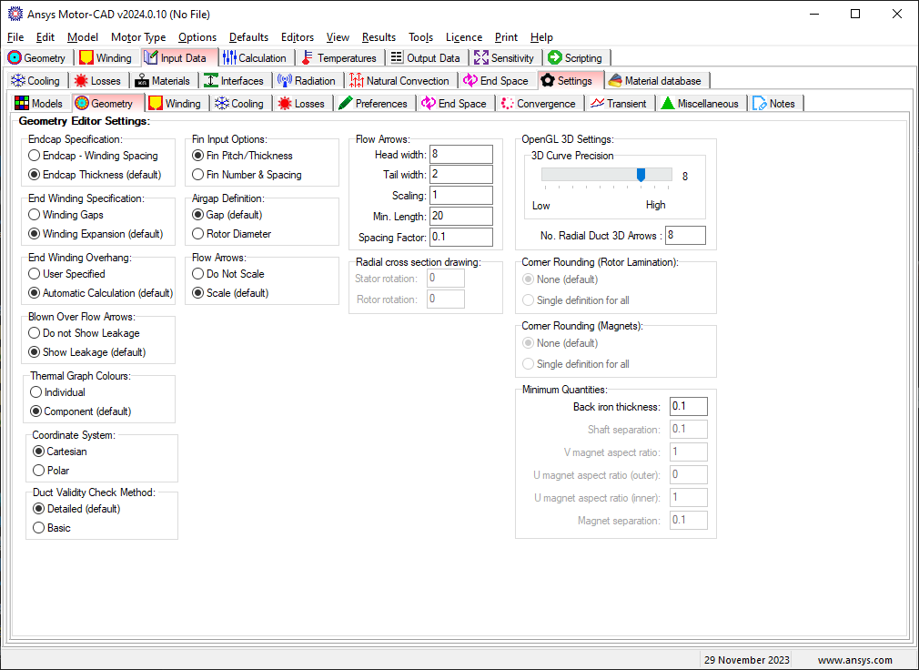
The editor has options to change the following model settings:
Endcap Specification
The endcap specificication option specifies how the endcap gap is specified, the same model is used when using either option. By default the new method uses Endcap Thickness.
- Endcap - Winding Spacing - Use winding spacing to define the endcap.
- Endcap Thickness (default) - Specify the endcap thickness directly.
End Winding Specification
The end winding specification option specifies how the end winding gap is specified, the same model is used when using either option. By default the new method uses Winding Expansion.
- Winding Gaps - Use winding gaps
- Winding Expansion (default) - Use winding expansion to specify gaps.
End Winding Overhand
The end winding overhang option specifies whether the end winding overhang length is to be specified by the user or automatically calculated in Motor-CAD. The automatic calculation option is available for BPM, IM, SRM, BPMOR, SYNC and IM1PH motor types. When the automatic calculation option is set, additional multiplicative factors can be specified in the axial cross section editor. Details of the calculation are given in End Winding Overhang Calculation.
- User Specified - User specified end winding overhand.
- Automatic Calculation (default) - Automatically calculate the end winding overhang.
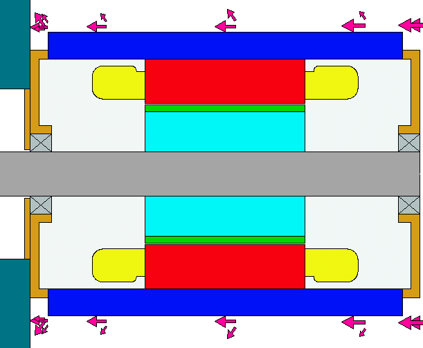
Blown Over Flow Arrows
The flow arrows shown in axial cross section view can be set to give an indication of the leakage from the blown over surface as shown below.
The leakage values are taken from the blow over fluid flow page.
- Do not Show Leakage - Leakage arrows not shown.
- Show Leakage - Leakage arrows shown.
Thermal Graph Colours
- Individual - each plot has a different colour
- Component - the plots are given colour that match the machine component colours. e.g housing plots are drawn in blue.
Coordinate System
The coordinate system used within the Geometry Editor.
- Cartesian - Use Cartesian coordinate system (x, y).
- Polar - Use Polar coordinate system (r, t).
Duct Validity Check Method
The method used to check whether duct locations are valid within the machine.
- Detailed - Use detailed checking, this option checks whether all ducts of each layer are completely within the parent region, e.g. rotor ducts within rotor/shaft regions, including checking sub regions.
- Basic - Use basic checking, this option does a simple check using the duct and parent radii to ensure they do not overlap, this therefore does not take into account sub regions.
Fin Input Options
- Fin Pitch/Thickness:
In the original version of Motor-CAD the dimensions of fins placed on the housing were defined using the following parameters:
- Fin Thickness
- Fin Pitch/Thick
The advantage of the above parameters was that as the machine diameter was scaled up and down then the number of fins would be increased or decreased automatically. The disadvantage was that some thought is required when putting in the dimensions for an existing finned housing. In such cases often the number of fins and the fin spacing is known - this is why the new option to input the fin dimension using these parameters was added.
- Fin Number & Spacing:
In this case the user inputs the:
- Fin Thickness
- Fin Number [Quadrant]
- Fin Spacing [Fin Base]
See Fin Geometry for the geometry definitions.
Flow Arrows
The flow arrows scaling option scales the flow arrows based on the proportion of the flow in the different paths. This can be particularly useful for the through ventilation model. This scaling can be enabled and disabled here.
- Do not scale - Flow arrows not scaled.
- Scale (default) - Flow arrows scaled.
The flow arrows sizes displayed in the radial and axial cross sectional views (see Machine Cooling Flow Paths) can be set using the above interface.
The head width is the relative width (based on airgap size) of the arrow head.
The tail width is the relative width (based on airgap size) of the arrow tail.
The no. per flow and min length specifies the desired arrow length. If the requested number of arrows and minimum arrow length is not suitable for the length available then the number of arrows will be reduced.
The Spacing Factor is the distance between the arrows.
Airgap Definition
- Gap - the airgap is specified by the stator bore and the gap distance
- Rotor Diameter - the airgap is specified by the stator bore and rotor diameter.
Radial Cross Section Drawing
Rotor rotation
Allows the rotor position to be changed in the radial cross section view. This can be useful for matching the model with a DXF drawing.
Stator rotation
Allows the stator position to be changed in the radial cross section view. This can be useful for matching the model with a DXF drawing.
OpenGL 3D Settings
The 3D view is drawn using an OpenGL interface. The 3D curve precision setting allows the precision of the curves to be increased or decreased if the computer graphics card is having problems rendering the 3D image.
Corner Rounding (Rotor Lamination)
This option is available for U-shape and V-shape magnet geometries for BPM machines. When enabled an additional Rotor Lam Corner Radius field is available in the radial cross section editor.
- None (default) - No corner rounding applied.
- Single definition for all - Apply corner rounding to all vertices using a single definition.
Corner Rounding (Magnets)
This option is available for U-shape and V-shape magnet geometries for BPM machines. When enabled an additional Magnet Corner Radius field is available in the radial cross section editor.
- None (default) - No corner rounding applied.
- Single definition for all - Apply corner rounding to all vertices using a single definition.
Minimum Quantities
These values place are used in the calculation of geometry ratios and can be used to represent manufacturing tolerances or place further constraints on a design. Setting a constrain will cause a warning when it is not met and the geometry ratio is resized to a value that satisfies the constraint. A constraint is removed if put to zero.
Back iron thickness
The minimum allowable thickness of the stator back iron by limiting the maximum slot depth of the parallel slot and parallel tooth in the stator.
Shaft separation
This separation value determines the minimum distance between the rotor shaft and any other elements in the rotor such as rotor slots in SYNC machines, the rotor bars in IM machines or interior magnets in BPM machines.
Magnet aspect ratios
The aspect ratios limit the minimum ratio of magnet length to magnet thickness for the U- and V-magnets. The inner refers to the magnets centered in the middle and the outer to the outer left and right magnets.
Magnet separation
The magnet separation is the minimum allowable distance between interior magnet poles.
Sync Pole Surface Offset
The SYNC Pole Surface Offset option specifies how the pole surface offset is applied with SYNC beta rotor parameterisation enabled. More information can be found on the SYNC Rotor Parameterisation (Beta) Page.
- Ratio - The pole surface offset is applied and considered last. A Pole Surface Offset Ratio is used in Ratio Mode.
- Absolute - The pole surface offset is considered from the start and is shown as an independent parameter in Ratio Mode.
For other model settings see Settings[Input Data Editor].