


Blown Over Fluid Flow
This interface is used to define how the blown over flow changes as the fluid passes along the outside of the machine.
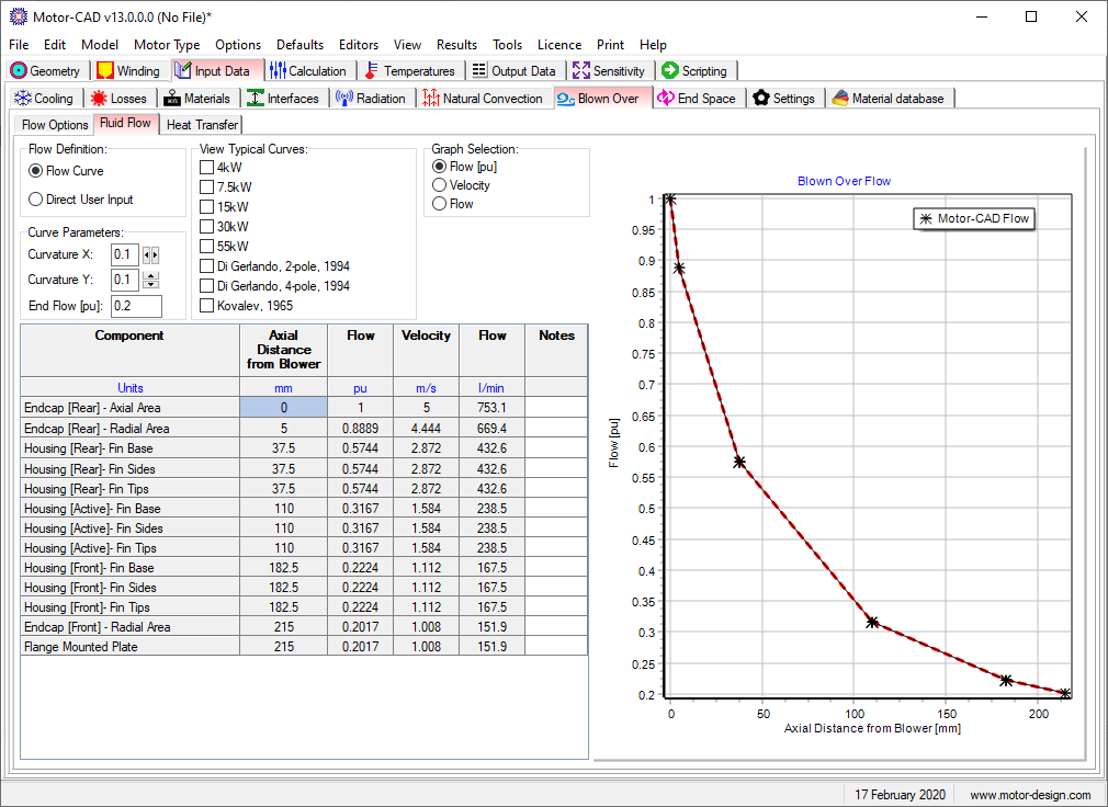
The flow can be specified using the Flow Definition to be either:
- Flow Curve - the user specifies a Bezier curve given by Curvature X and Curvature Y and End Flow values.
- Direct User Input - the user can specify the per unit flow along the axial length of the machine. This can be useful if the housing geometry is non standard giving different flow effects.
The Graph Selection option allows the graph to show Flow, Velocity or Flow Rate values along the axial length of the housing.
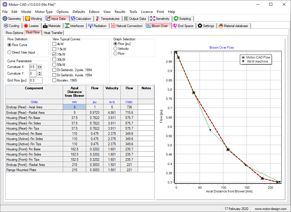
The View Typical Curves option allows the user to see the curves from different results so that their flow values can be compared and adjusted if necessary to match these results. The example below shows how the flow in the model is matched to the flow of a 15kW machine. The red dashed line will be used in the Motor-CAD model.
See also Blown Over [Input Data Editor], Blown Over Flow Options and Blown Over Heat Transfer