
Importing Twin Builder Models
Twin Builder lets you import multiple models and symbols, as well as create or update multiple components using the imported models and symbols. The following simulation model file types can be imported:
- VHDL Models (VHD)
- VHDL Encrypted Models (VEM)
- SPICE Subcircuits (CIR, LIB, SPC, SPI, MOD)
- SML Models (SML)
- C-Model Dlls (DLL)
- Modelica Models (MO, MOC)
- External Compiler Model Dlls (DLL)
Additionally, SVG Symbols (SVG) can be imported.
Follow this procedure to import simulation models into a Twin Builder project:
- Select Tools > Project Tools > Import Twin Builder Models. A file selection dialog box appears in which you can browse to the file containing the models to import.
- When you have located the desired model
file, click OK.
Note:
The location of imported CModel DLL files is set in the Twin Builder Options panel.
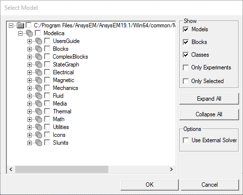
Note:For a Modelica import, a Select Model dialog box appears showing the models, blocks, and classes contained in the selected model or package file. It shows the complete package hierarchy if the selected file is from the library. Review the package hierarchy and choose the desired model, block, or class.
Select Use External Solver to enable simulation of the selected model using an external solver. The component of selected model will include the following properties that are used to control the usage of the external solver:
_cs_solver – Solver used in Co-Simulation. 0 - CVode, 1 – fixed step-size explicit Euler
_cs_rel_tol – relative tolerance when CVode is used
_cs_step_size – step size for Explicit Euler
When finished, click OK.
After model compilation, select the model interfaces you want to expose in the Twin Builder component. See Selecting Component Interface for detailed information.
A progress dialog box shows compilation progress of each model. Click Stop to end the compilation progress, ignoring the remaining models. Models compiled before you clicked Stop are imported.
The Import Components dialog box appears.
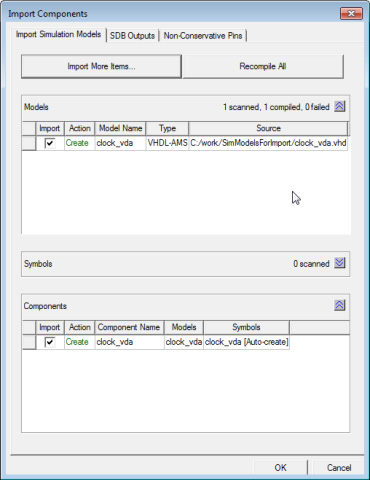
- The Import Simulation Models tab Models area lists the models that can be imported, provides an Import check box, lists the model Type (SML, VHDL, and so on), and the Source path. If a model already exists, the Action field indicates that the model will be updated; while for new models, it indicates that a model will be created.
If a model fails to compile, the dialog box shows failed status for that model, and a new failed simulation model tab is added to the dialog box listing the error messages for each failed model.
- Similarly, the Components area lists the components available for Import by name. If a component already exists, the Action field indicates that the component will be updated; for new components, it indicates that a component will be created. It also provides a button for choosing a Symbol for the component from the symbol library; and a button for choosing a Model for the component. The buttons display the names of the model and symbol currently associated with the component.
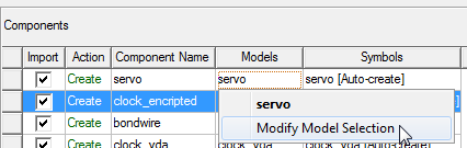
To add models to a component in the panel:
- Find the component to which you want to add more models, then click Models > Modify Model
Selection.
- The Modify
Selection dialog box displays, listing all available imported
models with compatible interfaces in the left box. Use the arrows to
move selected models to the right list-box. To select models from a
library, click Select From Library.
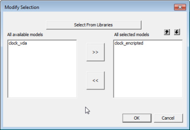
- Click OK to add all selected models to the component.
- An SVG image file associated with a model name, and residing in the same folder as the model will be imported and attached to the component. For example, if you upload C:\Lib_Model\Upload\simmodel1.vhd (containing a model named “simmodel”), and if there is an SVG file associated with the model name in any of the following scenarios:
- C:\Lib_Model\Upload\simmodel.svg (Same folder as the model file)
- C:\Lib_Model\Symbol\Simmodel.svg (Same folder level as the model file’s folder)
- C:\Lib_Model\simmodel.svg (One level above the model file’s folder) - the svg file will be attached to the component.
- The Symbols
panel is minimized by default. Click
 to expand the panel and view
its contents.
to expand the panel and view
its contents.
To change the symbol selection for a component:
- Click the Symbols field of the component whose symbol you want to modify to open a drop-down list and select Modify Symbol Selection.
- The Modify
Selection dialog box displays all available .svg symbols in the left box. Use the
arrows to move the selected symbol to the right box. To select symbols
from a library, click Select From Library.
Note:
Components can have only one symbol.
- Click OK to add the selected symbol.
- Click Import More Items to add more models from other folders.
- A button lets you Recompile All the models in the Models area. You can also select models in the list and Recompile Selected models.
- Ensure that the Import
box next to each model and component you want to create is checked.
Note:
If you choose not to create a component, the source files will be compiled – no component is created.
- On the SDB tab, select the quantities and signals you want to set as default outputs for each created component. By default all signals are selected.
- On the Non-Conservative Pins tab, select the non-conservative quantities and signals for which you want pins included on the new component symbol. All terminal pins are added by default; and all signal pins are selected by default.
- Click OK to create a component for each imported model.
The new components and models are added to the Components and Models folders within the current project’s Definitions folder in the Project Manager.
New models are also added to the list of Project Components on the Component Libraries Components tab where they can be placed onto a schematic for simulation.
For Modelica models, extra parameters are added for initializing input values. See Compiling and Updating a Project to Add a Modelica Model and Component for more details.
Handling of Incompatible Definition Names during Simulation Model Import
The syntax rules for definition or instance names in other simulation tools may be different from those in Twin Builder, which may make them incompatible with Twin Builder. For that reason Twin Builder applies some algorithms to make the names compatible with the Twin Builder syntax rules. The most common case for this to happen is during the import of Spice/PSPICE models.
- If the name starts with a number, an underscore (_) is prepended
- Any character inside a name that is any of [a-z][A-Z][0-9][_] is replaced by its ASCII representation (for example, "&" is replaced by "_ASC38_")
- Some special cases commonly used in Spice models:
- Numbers used as net names: N_ is prepended.
- The minus sign (-) is replaced by _M_.
- The plus sign (+) is replaced by _P_.
Related Topic
Using the Compile & Update Project Command in a Model Editor