
Using Layout Custom CS for Placement in HFSS 3D
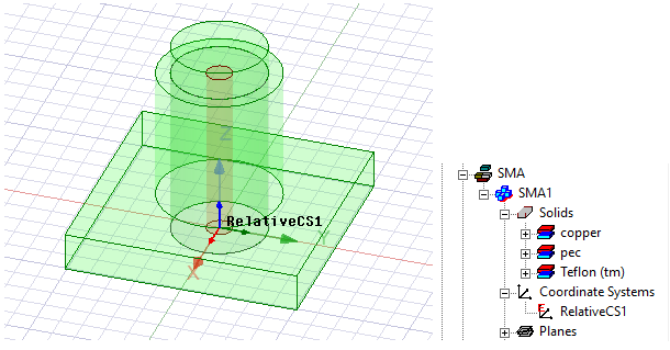
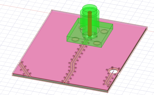
The ability to define coordinate systems in layout facilitates placing a layout component on a desired location relative to other geometry. In this example illustrates a 3D component (shown in green) that comes with a CS called “RelativeCS1”. This CS is located at the bottom of the component and at the center of the internal cylinder structure.
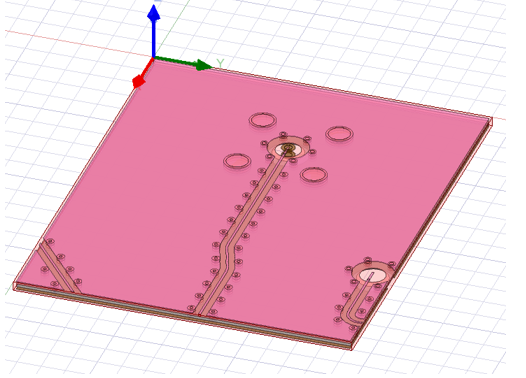
We also have a layout component shown in red. In the original layout design of this component, the global CS is located at one of the centers of the entire structure. Without this feature, when you create such a layout component in HFSS, its global CS will be used as the reference CS.
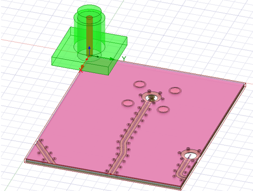
In this example, you want to place the layout component under the 3D component so that its holes (in the middle of the component) are aligned with the hole from the 3D component. When you import the layout component in Maxwell using its global CS as the reference CS and “RelativeCS1” as the layout component’s target CS, it snaps the layout component’s global CS to the target CS, which will look like the figure below.
In the original layout design, there is another CS at the center of the holes called “CS_1." When you import the layout component, select this new CS as the reference CS.
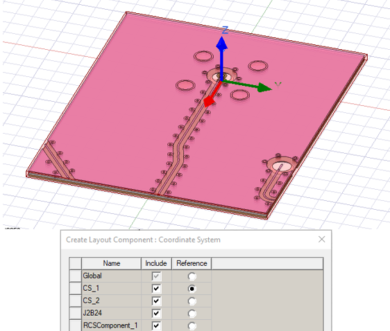
Using this new reference CS, the select the target CS as “RelativeCS1”.
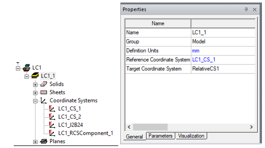
The layout component is now in the right place where its reference CS “CS_1” snaps to the target CS “RelativeCS1.”.
Related Topics
Using Layout Component in HFSS 3D Process Flow
Visualization for Layout Components in HFSS 3D
Visualization for RLC Boundaries and Component Groups Designated as Circuit Elements
Replacing or Editing Layout Components
Using Layout Custom CS for Placement in HFSS 3D
Flex PCB Components in HFSS 3D
Field Plots on Layout Component's Layer or Net
Using the Fields Calculator with Layout Component in HFSS 3D