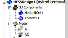
Create Array Command for Native Geometries
The Create Array command is enabled for Modal and Driven Terminal problems for the HFSS with Hybrid and Arrays Solution Types after you have assigned Primary and Secondary lattice pair boundaries to your unit cell model. You can access the command in three ways: click HFSS>Model>Create Array, right-click the Model icon in the Project tree and select Create Array... from the shortcut menu, or select the unit cell in the modeler window, and select Create Array ...from the short-cut menu. You also have the option to Create Array Through CSV.... This option is useful especially for defining large-scale arrays when defining through the UI dialogs requires a lot of manual work. This section describes the Create Array.... command. The Create Array Through CSV... command is described in a separate section.
Create Array... Command Procedure
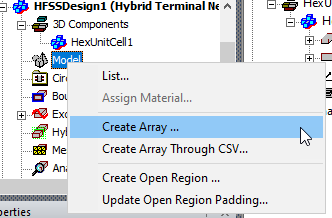
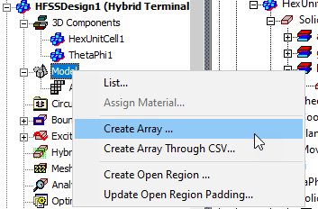
Right-click the Model icon in the Project tree and select Create Array... from the shortcut menu.
This displays the Regular Array dialog where you specify parameters for Number of Cells, Unit Cell Position and Lattice Vectors.
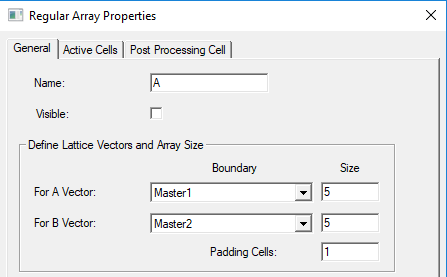
- If you have Visible enabled, you can see any changes.
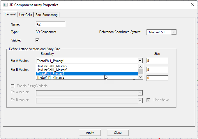
- To Define Lattice Vector directions for A and B Vectors, select the different primary boundary from the drop down list for each..
- To define the array size, for the A and B vectors, specify the number of cells for each row and column, respectively.
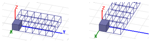
- For example, the
following figure shows the results when the initial Lattice Vectors are
swapped.
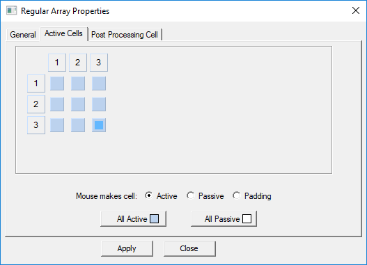
To create an irregular array, select the Active Cells tab, select the radio button for Mouse makes cell as Padding.
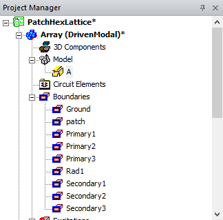
Once you have specified the parameters, the Array object appears in the Project tree under the Model. Only one Array is permitted for a model. The Create Array command is disabled if an array is defined.
By selecting the Array icon in the Project tree, you right-click for the short cut menu.
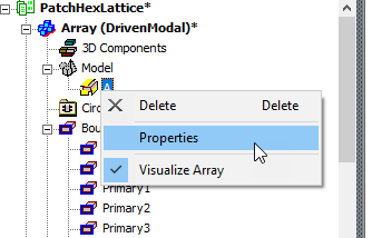
- Selecting Delete removes the array from the Model.
- Selecting Properties displays the Regular Array dialog.
- Selecting Visualize Array lets you toggle the array display. A check mark indicates that the array is being displayed.
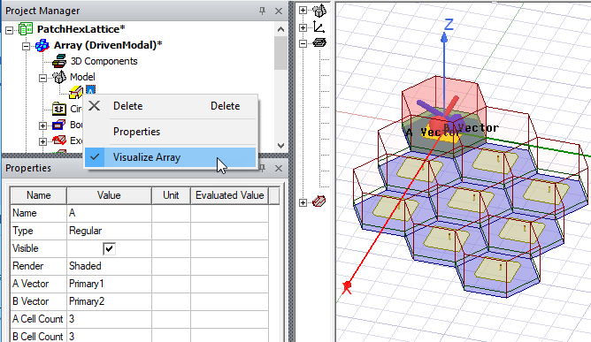
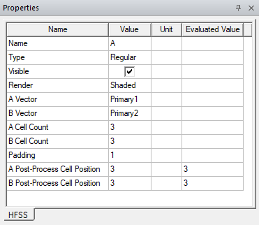
With the Array icon in the Project tree selected, if you have a docked Properties window displayed, you can see and edit Array Properties. All edits are undoable and informational messages will be posted to the Message window when design data is deleted.
Multiple Finite Arrays (Beta)
For some HFSS 3D problems like Z-axis stacked up arrays, or multiple arrays on the same platform, the HFSS Multiple Component Arrays Beta feature allows multiple array setups with the same UI access as you use to create a single array. You must define each array center position by different relative coordinate systems, and each array has its own lattice vectors, component list and array mask.
Each array must be enclosed by an airbox. If multiple arrays have different airboxes, each airbox must be assigned as FEBI. Multiple arrays cannot have contact with lattice boundary faces.
Creating Multiple Arrays
The process of creating each additional array uses the same commands as for creating a single array. Once you have a single array setup available, repeat the same array creation process by placing the Unit cell you want to use for the added array, and then select Model > Create Array …
In the 3D Component Array Properties dialog, first select the coordinate system that you associate with the Unit cell placement for the additional array.
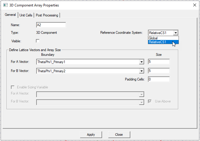
You can then select lattice vectors from available unit cell boundaries, and then define the array size and padding. A checkbox lets you make the array visible in the Modeler window.
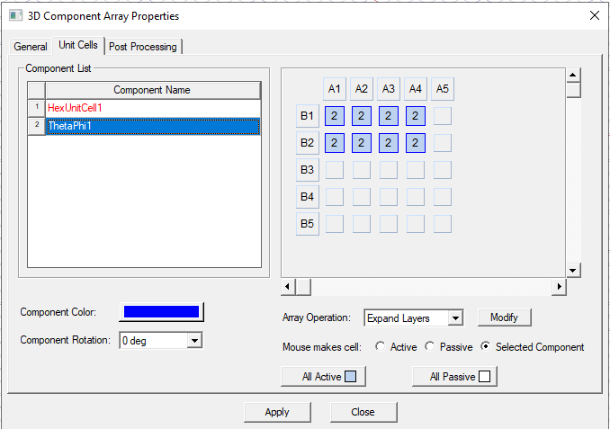
Then use the Unit Cells tab to select the array cells and define the component mask
The added array appear in the Project tree and, if you have enabled visualization, in the Modeler window.