Create Array Command for 3D Component
The Create Array... command is enabled for Modal and Driven Terminal problems with the HFSS with Hybrid and Array Solution Type, after you have inserted a 3D Component that has assigned Primary and Secondary boundaries to your original unit cell model. 3D Component Array has non-conformal mesh interface between unit cells, which greatly reduces the memory footprint and improves the performance. Once you have created a 3D Component Array, you can place it inside a region, and then assign a PML Boundary, a FEBI Hybrid Region, or a Radiation Boundary on the outside of the region. When a 3D component is placed inside of a region object, no native model object other than the region and its dependent objects are allowed.
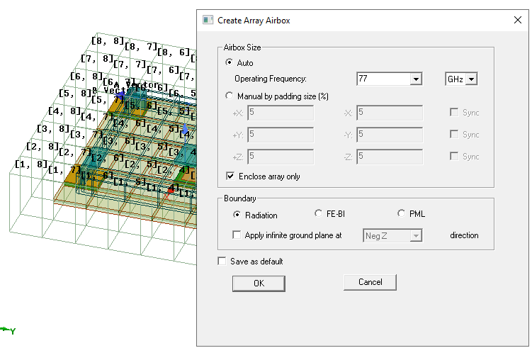
The Create Array Array Airbox Enclosure command is enabled after you have used the Create Array... command to describe the array and designate active cells. Given an existing component array design, you can add arbitrary native FEM geometries around the component array, as long as all geometries are enclosed by an airbox. This feature greatly expands the use cases of existing component array definition.
The Create Array Airbox dialog supports Auto definition of an airbox by frequency. It also has a checkbox to calculate airbox size based on either array itself, or array plus all FEM geometries.
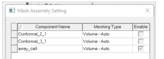
Component array design support non-array components (that is, components without at least two lattice boundaries). You can these components to array design just like native geometries. Mesh assembly is not supported in this case.
Component array design with surrounding geometries supports SBR+ regions. In this case, all geometries except SBR+ regions must be enclosed by an airbox. After you create a 3D Component array, you can define SBR+ geometry in 3D Component Array design to take advantage of leveraging the current component array and SBR+ techniques and workflows. This can provide significant enhancement to design and simulation efficiency. For use with SBR+ you must enclose the component array with an airbox and assign it as either FEBI, Radiation or PML.
See the SBR+ and 3D Component Array section for the process, which including automatic airbox create/update, array reference CS, and hybrid coupling dialog.
Multiple Finite Arrays (Beta)
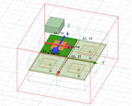
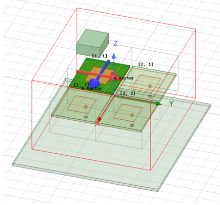
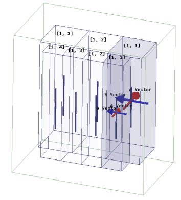
For some HFSS 3D problems like Z-axis stacked up arrays, or multiple arrays on the same platform, the HFSS Multiple Component Arrays Beta feature allows multiple array setups with the same UI access as you use to create a single array. You must define each array center position by different relative coordinate systems, and each array has its own lattice vectors, component list and array mask. You can define arrays within SBR+ Regions.
Each array must be enclosed by an airbox. If multiple arrays have different airboxes, each airbox must be assigned as FEBI. Multiple arrays can now have contact with lattice boundary faces.
Creating Multiple Arrays
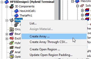
The process of creating each additional array uses the same commands as for creating a single array. Once you have a single array setup available, repeat the same array creation process by placing the Unit cell you want to use for the added array, and then select Model > Create Array …
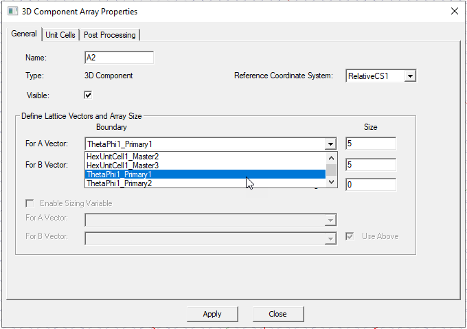
In the 3D Component Array Properties dialog, first select the coordinate system that you associate with the Unit cell placement for the additional array.
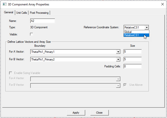
You can then select lattice vectors from available unit cell boundaries, and then define the array size and padding. A checkbox lets you make the array visible in the Modeler window.
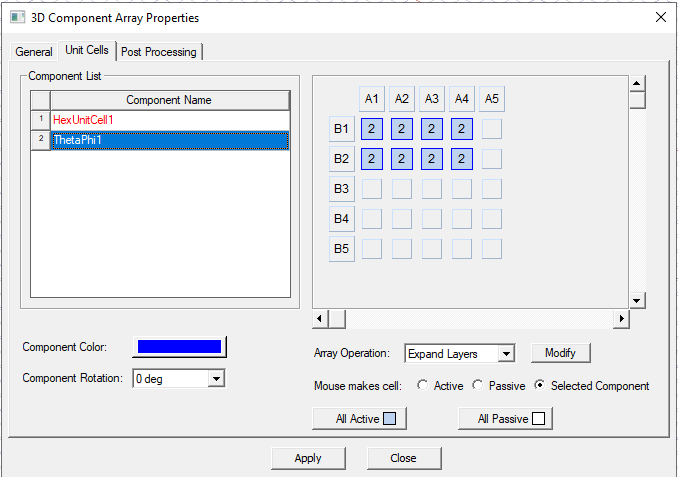
Then use the Unit Cells tab to select the array cells and define the component mask
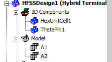
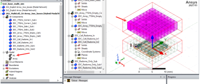
The added array appear in the Project tree and, if you have enabled visualization, in the Modeler window.
Copy/Paste for Arrays
Since multiple arrays are supported in HFSS, it’s natural to define new arrays based on existing arrays. HFSS supports array copy/paste like 3D component copy/paste. This operation first creates new array component instances and then duplicates array definitions, such as component mask and component rotation angles). By default, the pasted array uses the active coordinate system as the array reference coordinate system.
When the Beta feature for Multiple Arrays is not enabled, the copy/paste functionality still works if the pasted design does not have an existing array.
Array Component Highlighting
When you select an array item, all related components are highlighted. This new functionality works when the Beta feature for Multiple Arrays is off.
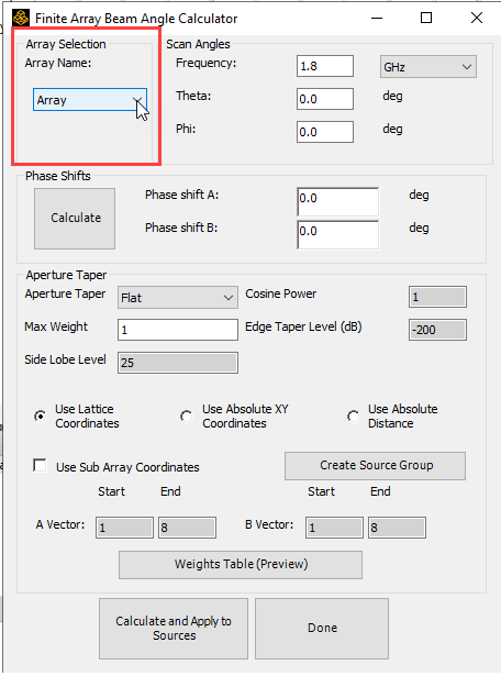
Multiple Arrays Beam Angle Calculator Toolkit
The Finite array beam angle calculator toolkit automatically calculates the edit source setting given aperture taper parameters and is very useful in array beam design. In 25.1 the feature extends to multiple array designs and each array can be calculated individually. When the Beta feature for Multiple Arrays is off, the new “Array Selection” control box still appears in the Toolkit, but only one array can be selected.