
Assigning PML Boundaries
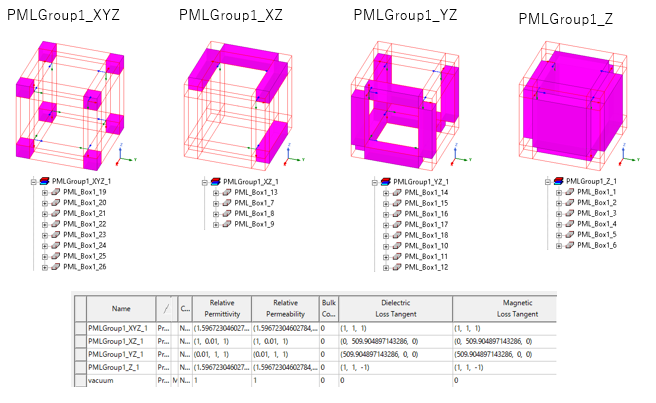
A perfectly matched layer (PML) boundary is used to simulate materials that absorb outgoing waves. Setting up a PML boundary is similar to setting up a radiation boundary. You start by selecting faces on the radiating object or by drawing a virtual object around the radiating structure. However, instead of placing a radiation boundary on its surfaces, you add PMLs to fully absorb the electromagnetic field. You can also assign PMLs to Region objects. Ansys Electronics Desktop can create PMLs automatically with the PML Setup Wizard, or using the Create Open Regions command, or you can create them manually. Create PMLs automatically if the base object touching the PML is planar and its material is homogeneous. HFSS creates a separate PML object for each covered face. The following figure shows PML objects automatically generated around a cubic region. The objects are grouped in the History tree as PML groups.
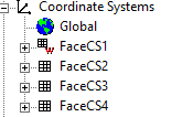
Each PML object is created on a Face coordinate system. You will see each FaceCS for PMLs listed under the Global CS.
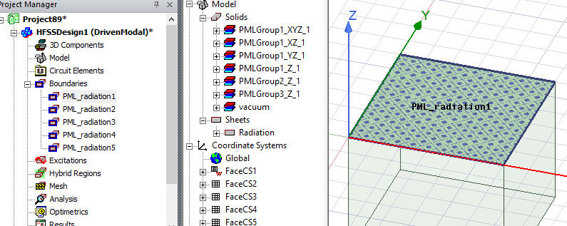
The PML boundaries are grouped in the Project tree under the Boundaries icon. Within these groupings, you can edit the radiation parameters (for example, as Incident Wave Port) in order to set up the right total field excitation based on the physical optics approach.
In creating PMLs, you can select non rectangular sheet objects as long as they do not touch any other selected face.
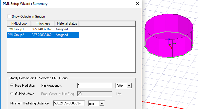
You can assign variables to the dimension properties of the base object. Changing the variable values then changes the associated PMLs. PML objects on a region are automatically updated when the region is updated by changing a region property or variable value.
Limitations
- If you do assign PML objects to a region, you cannot perform geometry operations or copy and paste operations on that region.
- Region-dependent CS cannot be set as current CS.
- PML radiation boundaries are not generated in Eigenmode projects.
- The underlying object for assigning PML Boundaries does not have to be a box. However, any touching faces must be locally box-like.
PML Compared to Radiation Boundaries
Compared to Radiation boundaries, which create absorbing boundary conditions (ABC), PMLs in general make it more difficult for the iterative solver to reach convergence compared to the same model with using ABCs. PMLs also require significantly more RAM. The advantages for PMLs are that they absorb a much wider range of waves in terms of frequency and direction. As a result, you can put PMLs much closer to the discontinuities. This gives a smaller model. ABCs efficiently absorb normal incident waves. You have to put ABCs far away enough from the discontinuities.
What do you want to do?