
Using the Maxwell Machine Toolkit Wizard (Windows only)
The Machine Toolkit wizard (Windows only) requires a valid 2D or 3D transient design with motion setup. The machine toolkit uses the original design to create a new design that is then used to perform the analysis. The machine toolkit supports five machine types:
- PM (Permanent Magnet) Synchronous Machines
- Induction Machines
- Synchronous Reluctance Machines
- Switched Reluctance Machines
- Wound-rotor Synchronous Machines
The machine toolkit can be used in the following four scenarios. Choose the one appropriate for your design needs.
Interactive Solve
- For interactive solve, define the machine parameters, then click Finish. The toolkit will solve the parametric table sweep and calculate efficiency maps immediately on the same machine. Make sure you have set the analysis setting you wish to use (DSO/HPC).Note: The user does not have to solve the parametric sweep, it is solved automatically.
- The toolkit creates a new design.
- Parametric sweep is solved.
- For PM Synchronous machines, Synchronous Reluctance machines, and Wound-rotor Synchronous machines: If not provided by the user, the DQ initial alignment angle is calculated by solving an independent simulation.
- Results are extracted.
- Postprocessing is performed, and reports (contour plots) are created in the design.
Delayed Solve
- For delayed solve, define the machine parameters, and check Solve for initial angle then prepare new design (user to solve parametric table).
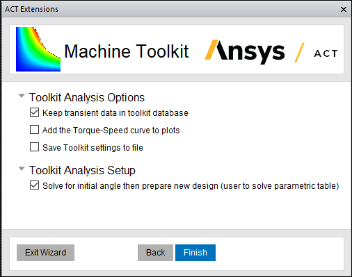
- Click Finish.
- A new design is created.
- For PM Synchronous machines, Synchronous Reluctance machines, and Wound-rotor Synchronous machines: If not provided by the user, the DQ initial alignment angle is calculated by solving an independent simulation.
- The parametric sweep is then solved separately by the user.
- After solving, reopen the toolkit. The parameter entries will be prefilled.
- Navigate to the last wizard page and select Use results of simulations to create efficiency maps and select the Solved Design to be used.
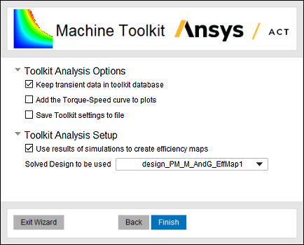
- Click Finish.
- Results are extracted.
- Postprocessing is performed, and reports (contour plots) are created in the design.
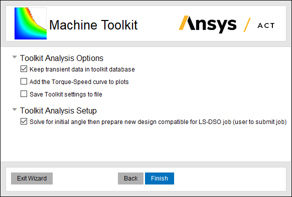
Solve using LS-DSO
-
For solve using LS-DSO, define the machine parameters, and check Solve for initial angle then prepare new design compatible for LS-DSO job (user to submit job).
-
Click Finish.
- A new design is created.
- For PM Synchronous machines, Synchronous Reluctance machines, and Wound-rotor Synchronous machines: If not provided by the user, the DQ initial alignment angle is calculated by solving an independent simulation.
- The new design contains a parametric sweep that needs to be solved.
- The toolkit stops to let user solve the LS-DSO job separately.
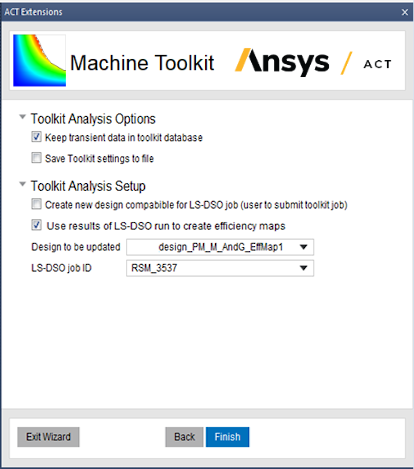
- Upon completion of the LS-DSO job, restart the toolkit. The parameter entries will be prefilled.
-
Navigate to the last wizard page and select Use results of LS-DSO run to create efficiency maps, then select the Design to be updated and also the LS-DSO job ID that was used for the job.
-
Click Finish.
- Results are extracted.
- Post-processing is performed, and reports (contour plots) are created in the design.
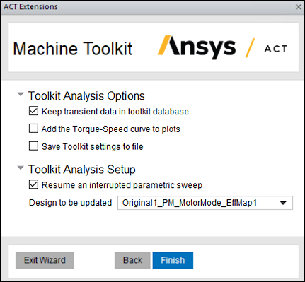
Resume an Interrupted Parametric Sweep Run
-
For this scenario, first select an existing original design. The parameters of the interrupted efficiency map design are automatically prefilled in the UI.
-
Navigate to the last wizard page and select Resume an interrupted parametric sweep and select the Design to be updated.
-
The parametric sweep of this design will start from where it was interrupted, and efficiency maps will be generated in post processing.
Generate Efficiency Map Only
- For this scenario, first select an existing design. The parameter entries will be prefilled.
- Navigate to the last wizard page and select Use results of simulations to create efficiency maps and select the Solved Design to be used.
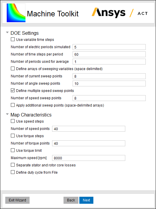
- Both general transient and periodic (or half-periodic) TDM can be used to conduct parametric analysis and create performance maps. Define the TDM option in the analysis setup of the original design. When conventional transient method or general transient TDM is used to extract performance data, it is necessary to define Number of electric periods simulated and Number of periods used for average in DOE settings. There is an option for the user to define two time intervals, and also specify the number of electric periods and number of time steps per period for each interval. When periodic or half-periodic TDM is enabled in the original design, such options are hidden in DOE settings, and the Machine Toolkit automatically defines the time duration for each simulation.
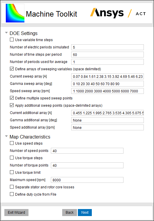
Machine Toolkit provides two options for the user to determine sweep points in the parametric analysis. The first option is to define the number of sweep points for each independent variable, and then Machine Toolkit assigns the sweep points that are uniformly distributed in the solution domain. The second option is to define the numerical arrays of the sweeping variables, where each value is separated from its adjacent values by a single space character.
Once the parametric analysis of the prior efficiency map simulation is completed, there is an option for the user to apply additional sweep points to the parametric analysis. The operating points that are already computed in the prior parametric analysis are automatically skipped, and Machine Toolkit only simulates these additional points.
Note: For an induction machine model with general transient analysis, the simulations of some operating points in the prior parametric sweep may not be skipped.TDM options cannot be enabled for Switched Reluctance machines.
For induction machines, to use periodic TDM or half-periodic TDM, all sources including induced eddy current have to be in the same frequency. This means periodic TDM or half-periodic TDM is only applicable when rotor is locked at zero speed. To this end, we can introduce equivalent conductivity σ_eq associated with locked rotor to approximate the performance at original speed (σ_eq = σ * slip). For this kind of equivalence, fundamental component will be correctly modeled. This approximation is normally good enough to the simulated performances including torque, current, voltage, etc with one exception that computed loss in the rotor needs to be rescaled in terms of slip.
The following steps must be done before proceeding to use periodic TDM solver in the toolkit:
- Add a project parameter called $slip. The Value and Evaluated Value can be any number since the parametric sweep will override it.
- Modify the rotor bar’s material, and change the conductivity from X to X*$slip.
- Modify the end connection resistance from X to X/$slip.
- Select Enable two level for HPC setting.
- Click Finish.
- Results are extracted.
- Post-processing is performed, and reports (contour plots) are created in the design.
Create Efficiency Maps based on Reduced-Order Model
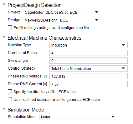
Machine Toolkit supports efficiency map generation based on the reduced-order model (ROM) for induction machines. This feature must be implemented in a design with Eddy Current solution type. The following parameters must be defined through the Machine Toolkit UI about the characteristics of the efficiency maps, including phase RMS voltage, phase RMS current, maximum torque and speed, core loss correction factor, control strategy, simulation mode, friction loss, windage loss and their reference speed.
Refer to the item ECEIM_Model for details about its input parameters and the mathematical representations of the ECE ROM for induction machines. All identified parameters of the ECE ROM are saved in the file ece_table.txt, and the Machine Toolkit needs this file to generate efficiency maps. There are three options for the user to obtain this file and define its directory in the Machine Toolkit. The first option is that the user directly specifies the file by checking Specify the directory of the ECE table. The second option is that the user first define an external circuit which includes an ECEIM_Model module, then the Machine Toolkit launches the analysis and automatically obtains the file ece_table.txt. The third option is that the Machine Toolkit creates an external circuit with the ECEIM_Model module and imports it to the definition of Excitations, then runs the simulation to get this table. Additional parameters must be input by the user if the third option is selected, including the skew angle, phase RMS current, number of current sweep points, and the resistance and end inductance of the windings. The user can also define the current sweep array for the ECEIM_Model:
Related Topics
Defining Machine Toolkit Parameters
Working with the ACT Extensions Window