
Defining Machine Toolkit Parameters
The ACT Extensions window and the design wizards it contains are only available for the Windows version of the Ansys Electronics Desktop software. These items are not available when the software is installed on a Linux platform.
The machine toolkit supports five machine types:
- PM (Permanent Magnet) Synchronous Machines
- Induction Machines
- Synchronous Reluctance Machines
- Switched Reluctance Machines
- Wound-rotor Synchronous Machines
The general workflow for using the Machine Toolkit to define machine parameters is as follows:
- In the ACT Extensions Wizards window, click on the Machine Toolkit icon to launch the wizard, and select a valid transient design with motion.
- You can open a project/design in the project manager if one is not already open.
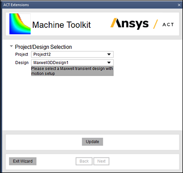
After loading the project, select Update to refresh the Project/Design selections.
- Select the desired project and design. Only designs that do not use reserved local variables are shown in the drop-down menu.
Reserved local variables are Speed_TSC, Imax_TSC, Gamma_TSC, Vmax_TSC, Slip_TSC, Freq_TSC, and Field_TSC.
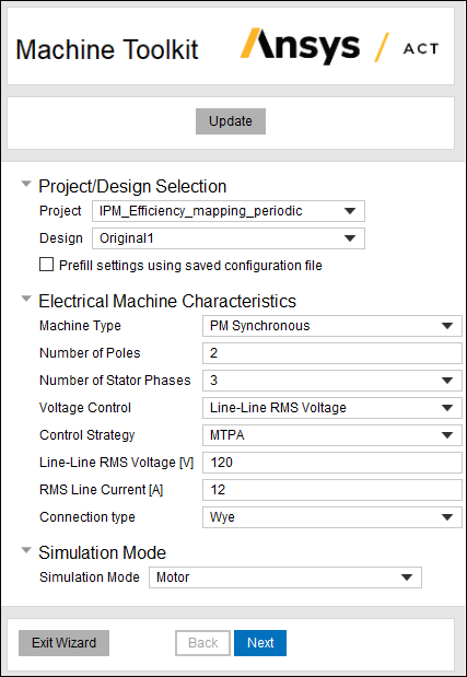
- Enter all characteristics of the machine: Machine Type (PM Synchronous, Induction, Synchronous Reluctance, Switched Reluctance, or Wound-rotor Synchronous), Number of Poles, etc., in the various fields. Also select the desired Simulation Mode (Motor or Generator).Note: You can prefill all settings using a previously saved configuration .sav file by selecting Prefill settings using saved configuration file.
If you have previously used the toolkit with the current project, the toolkit prefills entries automatically.
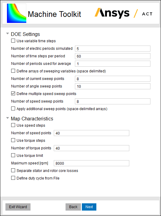
- Click Next to go to the next page of the wizard. Here you enter the desired DOE (design of experiments) Settings, and the Map Characteristics used to generate the efficiency map when the design is solved.Note: The content of the DOE Settings and Map Characteristics change based on which machine type you selected on the previous page.
Note that check boxes allow you to Use speed steps and Use torque steps instead of using the default speed and torque points. A parametric sweep will be created to account for the number of points (or steps).
- When finished, click Next to move to the next page of the wizard.
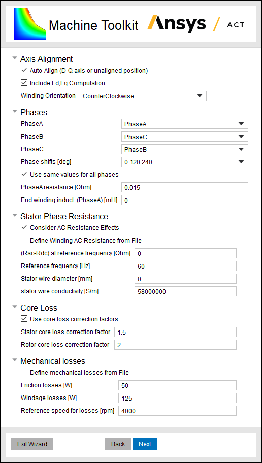
- For PM Synchronous machines, Synchronous Reluctance machines, and Wound-rotor Synchronous machines, you can provide the alignment angle or have the toolkit calculate it. No matter which simulation mode is chosen, the initial angle must be determined first.
- For Phases, provide phase names, phase shifts, and other phase information.
- Optionally, provide custom loss information (Core Loss, Stator Phase Resistance winding losses, and Mechanical Losses).Note: There are three options for AC winding loss calculation:
- Apply the analytical AC winding loss model, and the user is required to input the stator wire diameter and conductivity, as well as AC resistance at the reference frequency.
- Use the Litz wire model.
- Input a .txt file that provides a frequency vs. AC resistance table; in this file, the first line should include the names and units of frequency and resistance, for example, "Freq[Hz] Rac[ohm]", followed by combinations of frequency vs. resistance data in each line, for example, "60 1.5".
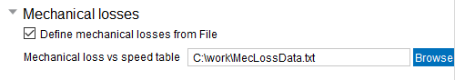
Note: Mechanical losses include friction and windage losses at a reference speed.You can optionally "Define mechanical losses from File", then specify the location of a user-defined “Mechanical loss vs speed table” text file.
- When finished, click Next to move to the next page of the wizard.
- It is recommended to have the Keep transient data in toolkit database option enabled to retain the data because the extraction process can be lengthy.
- Check Save Toolkit settings to file if you want to save all settings to a
.savfile for use with another project. (For the current project, the settings are saved automatically.) - Check Disable smoothing in post processing if you want to bypass the smoothing algorithm, which may improve the fidelity but increase the noise level of the data in the performance maps. You can also define the Number of processes in post processing depending on the CPU specifications, to enable parallel computing and reduce the simulation time for the optimization that searches for the optimal operating condition on each point in the performance maps.
- You can click Back to review or edit settings on previous pages.
- If you choose to Exit Wizard, all settings are automatically saved and loaded the next time the current project is loaded.
- Toolkit Analysis Setup options are used for the various scenarios described in Using the Maxwell Machine Toolkit Wizard.
- Click Finish to complete the process for the various scenarios as described in Using the Maxwell Machine Toolkit Wizard.
Related Topics
Using the Maxwell Machine Toolkit Wizard
Working with the ACT Extensions Window