
ECEIM Model
The ECEIM model enables you to create an ECE model of a three-phase induction motor from Maxwell Eddy Current solutions.
To change the name of the model placed on the sheet, click the symbol on the sheet, and change the name of the component in the property window (Value field in the DeviceName line, with the Parameter Values tab selected).
The ECEIM_Model contains the following parameters:
- DeviceName – the name of the device model with default name ECEIM_Model1.
- Windings – specifies the comma-separated name list of three-phase windings whose currents are to be swept.
- CurrentSweeps – specifies lists of sweep currents. The format is: “v1, v2, (dv1, n1), v3, …”, where v1, v2, v3 specify individual sweep values, and (dv1, n1) specify a sweeping range with dv1 being the increment, and n1 the number of increments. For example, a list of “-2.5 A, (0.5 A, 10)” is equivalent to "-2.5 A, -2 A, -1.5 A, -1 A, -0.5 A, 0, 0.5 A, 1 A, 1.5 A, 2 A, 2.5 A", and a list of "(0.5 A, 5)" is equivalent to “0, 0.5 A, 1 A, 1.5 A, 2 A, 2.5 A”.
- SkewAng – specifies the skew angle (in mechanical degrees) of the stator or rotor core for 2D only (available when Show Hidden is checked).
- Res – phase winding resistance (available when Show Hidden is checked).
- IndE – phase end-leakage inductance (available when Show Hidden is checked).
The ECEIM model is used to set up the sweeping of currents in three-phase windings. A slip sweep is added together with the current sweep. The slip sweep is fixed (not user-configurable) with a list of the following 13 values: 0.01, 0.02, 0.04, 0.1, 0.2, 0.3, 0.4, 0.5, 0.6, 0.7, 0.8, 0.9, 1.0. To simulate the real operation of induction motors at a specified slip with Eddy Current solvers, the rotating rotor is treated as a locked rotor with equivalent rotor resistances and inductances.
An ECEIM_Model can be used individually to create the ECE model of a three-phase induction machine, or combined with the ECEF_Model for sweeping frequency.
At Maxwell run time, the circuit simulator assigns current, slip, as well as frequency if ECEF_Model is added, to Maxwell Eddy Current solver until all sweeps are finished. An ECE model is then created automatically. You can import this ECE model in Twin Builder via the Twin Builder > SubCircuit > Maxwell Component > Add Equivalent Circuit menu command. For more information on coupling Maxwell designs to Twin Builder components, refer to the Maxwell Equivalent Circuit Component topic in the Twin Builder Help.
For more information on coupling Maxwell designs to Twin Builder components, refer to the Coupling Maxwell to a Twin Builder Component topic in the Maxwell Help.
Circuit and Parameters
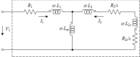
Due to saturation and skin effects, the stator leakage inductance might be nonlinear, and the rotor leakage inductance will be nonlinear and slip dependent. The rotor leakage inductance can be decoupled into two parts, nonlinear only and slip dependent only, as explained below.
The stator and rotor nonlinear can be expressed as

where

The slip-dependent rotor resistance and leakage inductance are

where

with

In the above equations, I1 is the stator phase current and s is the rotor slip, L10, L1m, L20, L2m, IT1, IT2, R2s0, L2s0 and ξ0, as well as R2 in the circuit, are 10 constant parameters identified from the eddy-current FEA solutions at different stator currents and rotor slips. If the stator or rotor leakage inductance is constant, L1m or L2m is zero, and I1T or LT2 is not used in such a case.
The nonlinear main inductance in the circuit is expressed as

where, Lm0 is a constant parameter, and ksm is the saturation factor of main field which is expressed as a look-up table. Both Lm0 and ksm are identified from the eddy current FEA solutions with different stator currents at no-load operation (with rotor slip being near zero).
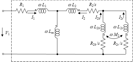
Because R2s0 and L2s0 are slip dependent, the above circuit can be implemented in the frequency domain only. If the rotor bar is divided into two sections with top section ratio of k1, and the bottom section ratio of k2 =1 – k1, the resistance and self-inductance of the top section will be

and the resistance and self-inductance of the bottom section are

The mutual inductance between the top and bottom sections is

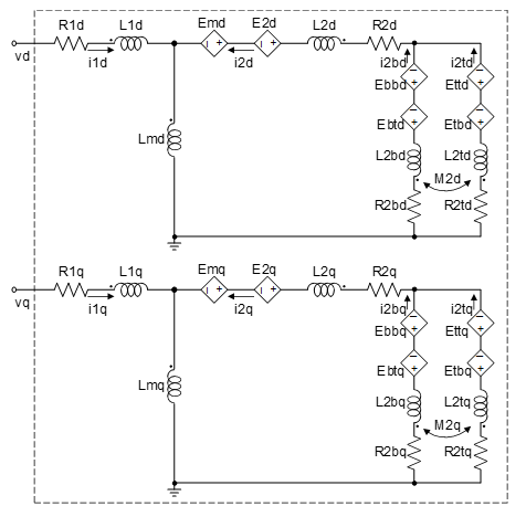
The circuit with distributed rotor sections is shown in the following figure:
After all parameters in the first circuit are identified, the top section ratio k1 is identified by minimizing the error of the impedance between the two circuits. All identified parameters are saved in file ece_table.txt, as shown in the figure below.
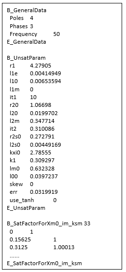
In above figure, r1, l1e, and skew are directly obtained from ECEIM_Model inputs Res, IndE, and SkewAng, respectively, 10 parameters, l10, l1m, it1, r20, l20, l2m, it2, r2s0, l2s0, kxi0 (ξ0), and lm0, as well as the look-up table between B_SatFactorForXm0_im_ksm and E_SatFactorForXm0_im_ksm, are identified based on the first circuit, and k1 is identified based on the second circuit. Parameter l00 is the zero-sequence inductance. The err value represents the relative error of impedances between the FEA solutions and the parameter-derived results. If the value of use_tanh is 1, the saturation factors for the stator and rotor leakage inductances will be expressed as:

to achieve smaller identification error, where tanh() is a hyperbolic tangent function.
Core Loss Parameters
Core losses can be computed for each sweep in eddy-current solver. To include core loss computation, users must check the Core Loss setting in the Excitations/Set Core Loss panel. Since core losses are computed in a post-process, including core loss computation will not affect the parameter identification of the induction machine circuit.
The stator and/or rotor core losses can be obtained from lamination steel or power ferrite material. For lamination steel material, the stator core loss can be computed from the phase circuit variables and expressed as:

where khs, kcs, and kes are to-be-determined parameters, Em is the phase induced voltage magnitude, and f is the frequency. For power ferrite material, core loss is expressed as:

where Cm, A, and B are to-be-determined parameters. The three parameters for either material can be identified at different induced voltage magnitudes and different frequencies by minimizing the error of core losses between the FEA solutions and the results obtained from the above equations. One of the above two equations will be automatically selected according to their identified errors. If the identified error based on the first equation is smaller than that based on the second equation, the first equation for lamination steel material will be selected. Otherwise, the second equation for power ferrite material will be selected. The core loss resistance is derived from core loss, and for lamination steel material, it is given by:

For power ferrite material, core loss resistance is given by:

Replacing Em by sEm and f by sf, where s is the rotor slip, we can calculate rotor core loss in the same way as the stator core loss. Then the rotor core loss resistance for lamination steel material is:

and the rotor core loss resistance for power ferrite material is:

Core loss resistance is frequency-dependent. In a time-domain circuit, as shown in the following figure, what we can measure are time-instant values. In order to use frequency-dependent resistance in a time-domain circuit, we need to calculate the frequency based on measurable time-instant values.
By measuring the induced voltages across Lmd and Lmq at time t, noted as Vmd and Vmq, respectively, we can compute the magnitude of induced voltage as:

Similarly, by measuring the flus linkages of Lmd and Lmq at time t, noted as lmd and lmq, respectively, we can compute the magnitude of flux linkage as:

The frequency then can be obtained from:

and the induced voltage magnitude in three-phase side Em for core loss resistance computation can be obtained by Vm with a factor of two-phase to three-phase transformation. The slip s for the computation of rotor core loss resistance can be obtained from the number of poles, rotor speed, and frequency.
The identified core loss parameters are listed between B_CorelossParam and E_CorelossParam in ece_table.txt file, as shown below.
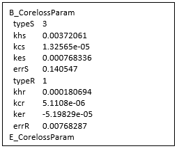
In the above figure, parameters typeS, khs, kcs, kes, and errS are for stator core loss. When typeS is 0, the circuit model will not include the stator core loss. When typeS is 1 or 3, the parameters are lamination-steel-based, and when it is 2 or 4, the parameters khs, kcs, and kes represent Cm, A, and B, respectively, for power ferrite material. When typeS is 1 or 2, two stator core loss resistances are connected in parallel with Lmd and Lmq, otherwise, when it is 3 or 4, two core loss resistances are connected from the input nodes of L1d and L1q to the ground. The errS value is the regression error for the stator core loss. Similarly, parameters typeR, khr, kcr, ker, and errR are for rotor core loss with the same definition as the parameters for stator core loss.
Since core loss parameters are identified from Maxwell eddy-current solutions at no-load operation based on the method referring the rotor frequency from the real operation condition to a locked-rotor operation (called locked-rotor method), the predicted core loss from the identified parameters will be under-estimated due to the following approximation errors:
- The error caused by field difference between no-load and load operations. At no-load operation, the field in an induction machine is mainly the main flux which links both the stator and rotor windings, while at load operation, the main fluxes created by the stator and rotor currents will mostly offset each other, remaining large leakage fluxes which will go through the stator and rotor tooth tips. In the stator, the leakage flux will add to the main flux, causing the stator core loss increasing. In the rotor, the leakage flux will partially cancel the main flux, causing the rotor core loss decreasing a little.
- The error caused by difference between sinusoidal (eddy-current solver) and non-sinusoidal (transient solver) waveforms. In eddy-current solver, core loss is computed based on pure sinusoidal waveforms, but in transient solver, core loss is computed based on real non-sinusoidal waveforms due to nonlinearity. The harmonic field components will cause additional core losses in both stator and rotor cores in transient analysis.
- The error caused by difference between locked-rotor and rotating operations. When rotor is rotating, the slot effects will cause additional core losses at the surfaces of the stator and rotor cores known as surface losses, as well as additional core loss at teeth of the stator and rotor cores known as pulsation losses.
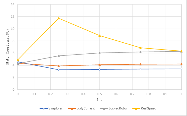
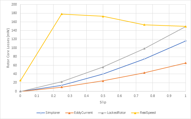
The above three loss errors can be illustrated by the following two figures for stator and rotor core losses, respectively. In the figures, curves labeled with “Simplorer” are obtained from the system simulation based on the extracted core loss parameters, curves labeled with “EddyCurrent” are obtained from the eddy-current simulation based on the locked-rotor method, curves labeled with “LockedRotor” are obtained from the transient simulation based on the locked-rotor method, and curves labeled with “RealSpeed” are obtained from the transient simulation with real rotor speed. The loss difference between curves “EddyCurrent” and “Simplorer” represents the error described in (1), the loss difference between curves “LockedRotor” and “EddyCurrent” indicates the error described in (2), and the loss difference between curves “RealSpeed” and “LockedRotor” is the error described in (3), which will increase as the stator currents increase, and will decrease as the rotor speed decreases.
Therefore, compare to Maxwell transient analysis, the core loss obtained from the circuit simulation will be under-estimated, especially at load operation. To adjust the simulated core loss, we introduce an argument KPfe in SIMPLORER (Twin Builder) circuit model to scale core losses for both stator and rotor. The default value of KPfe is 1.0. The reasonable value of KPfe at full-load operation may range from 1.5 to 2.5.
Since the stator and rotor core loss resistances are nonlinear and frequency dependent, we allow users to consider or not consider core loss effects on circuit variables to avoid possible divergence during circuit simulation. When we input a positive value for KPfe, we will consider core loss effects by connecting the core loss resistances with derived values. When the input value for KPfe is negative, the core loss resistances are disconnected.
No matter core loss effects are considered or not, the stator and/or rotor core losses are output via circuit arguments Pfe1 and/or Pfe2 in the SIMPLORER (Twin Builder) circuit model.