
Rotating or Spinning the View
You can rotate the view relative to the Model Center, the Screen Center, the Current Axis (that is, the active coordinate system origin), or the Cursor location. You can activate the rotation modes via the menu bar, ribbon tabs, or shortcut menu. When a Rotation command is active, you can click and drag using the left mouse button to manipulate the model viewpoint.
Rotation Using Only the Mouse: You can use the middle mouse button to rotate the view without selecting a Rotation command. From the menu bar, click View > Options to access the General tab of the 3D UI Options dialog box. Here, you can choose the desired Default Rotation About option. The view rotates about the Screen Center by default. The other available options are rotation about the Model Center, Current Axis (active coordinate system origin), or Cursor location. This setting also controls the rotation center for the Spin command.
Rotation using Only the Keyboard: You can use the key combination Alt + arrow keys to rotate the model view about a vertical or horizontal axis. Similar to using the middle mouse button, the center of rotation, through which the vertical or horizontal rotation axis runs, is determined by the Default Rotation About selection in the 3D UI Options dialog box.
For each active Rotation command, or when using the middle mouse button, the behavior differs depending on where you click and drag, as follows:
- Click and drag the cursor near any border of the Modeler window's display area:
- Click and drag the cursor within the interior of the display area (not close to a border):
- Click and drag on or near the View Orientation Gadget to freely rotate the view:
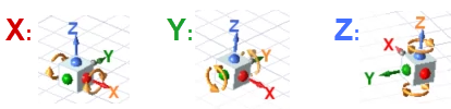
- Constrained rotation about the X, Y, or Z axis:
- X + click and drag to rotate the view orientation about the active X axis.
- Y + click and drag to rotate the view orientation about the active Y axis.
- Z + click and drag to rotate the view orientation about the active Z axis.
- For best results, drag the cursor in a roughly circular path around the rotation centerpoint. The model orientation will follow the cursor movement, with the angle of rotation matching the angle of the cursor's arc about the same centerpoint.
- Hold down the X, Y, or Z key throughout the constrained rotation operation. The axial rotation constraint is canceled as soon as you release the key, though the rotation mode remains active. Depending on how you initiated rotation, cancel it by either releasing the middle mouse button, pressing Esc, or clicking the command again.
- During an active constrained rotation operation, you can release the current hotkey and press one of the other hotkeys to choose a different rotation axis, without first canceling the operation.
- Rotating the view about an axis normal to the screen:
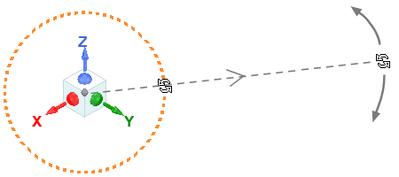
- Click anywhere on the circle: The model rotates 90 degrees clockwise.
- Ctrl + click anywhere on the circle: The model rotates 90 degrees counterclockwise. This action and the preceding one are particularly useful for changing the in-plane positive axis directions for standard top, bottom, left, right, front, or back views.
- Click and drag: Freely rotates the model in either direction. Release the mouse button when the desired orientation is reached. While the mouse button remains pressed, the cursor changes to a rotation icon:
The view is constrained to rotate about an axis that is perpendicular to the screen. The location of the axis, which is the rotation centerline, depends on the active rotation mode (Current Axis, Model Center, Screen Center, or Cursor) or, when no command is active, the Default Rotation About option previously described.
In this case, the view rotates freely about any axis, depending on the direction you drag and the relative positions of the cursor and center of rotation. The rotation center depends on the active rotation mode (Current Axis, Model Center, Screen Center, or Cursor) or, when no command is active, the Default Rotation About option previously described.
Use the following hotkeys to constrain rotation of the model viewpoint to be about a coordinate system axis (global or user-defined). These hotkeys work whether you perform the rotation using the middle mouse button, any of the Rotate commands available on the ribbon (under the View, Draw, or Model tabs), or any of the Rotate commands in the menu bar (View > Interactions > ...).
During constrained rotation, a heavy red (X), green (Y), or blue (Z) axis line appears in the Modeler window to provide a clear visual indication of the axis of rotation. These axes pass through the center of rotation, and this center is marked by crosshairs. When using the middle mouse button, the center of rotation is the centerpoint of the drawing canvas. For menu and ribbon commands, you can choose alternative rotation centerpoints (model center, cursor location, or origin), which are covered further down in this help topic. The following image shows the appearance of the rotation axes and center markers:
Additionally, a pair of gold, circular arrows appear on the view orientation gadget, indicating the axis of constrained rotation:
While the same constrained rotation functionality for 3D models is also available for 3D reports, the red, green, and blue axes do not appear in 3D report windows during axis-constrained rotation. However, the pair of circular, gold arrows appear on the view orientation gadget in both the Modeler and 3D Report windows to indicate the axis of constrained rotation.
This feature provides a very convenient means of achieving the ideal model viewpoint for setup operations and for presentation purposes, giving you much more control than free rotation.
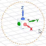
This orange dashed circle that appears around the view orientation gadget when the cursor is nearby is used to rotate the current view about the screen-normal axis. That is, the view rotation is constrained to the plane of the screen regardless of the current viewing direction. The line weight of the dashed orange circle becomes heavier when the cursor is touching it, indicating a correct clicking point. There are three actions, as follows:
You do not have to keep the cursor on the circle while dragging. You can often achieve more precise rotations with the cursor further away from the orientation gadget. Moving the cursor in a radial direction away from the center of the orientation gadget produces minimal rotation. Then, move it tangentially for precise rotation. The greater the distance from the gadget, the finer the rotational control.
To rotate the view about the Model Center:
- Choose the Model Center rotation mode using one of the following four methods:
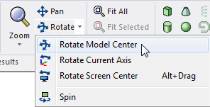
- From the View ribbon tab, choose Rotate:
- From the Draw or Model ribbon tab, choose Rotate > Rotate Model Center.
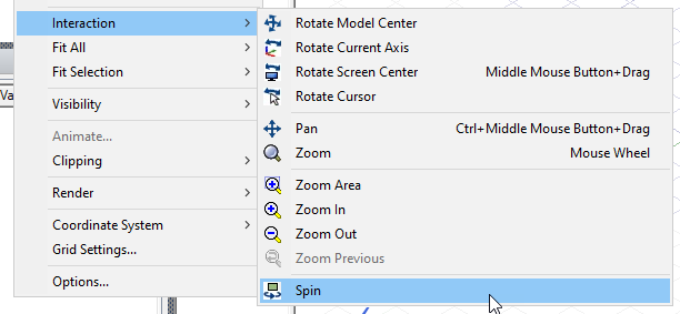
- From the menu bar, click View > Interaction > Rotate Model Center.
- Right-click in the Modeler window and choose View > Rotate > Rotate Model Center from the shortcut menu.
- Click and drag the mouse in the direction you want to rotate the view.
- To exit the rotation mode, click the command again (per step 1) or press Esc.
The Center icon on the View ribbon tab is for rotation about the screen center, not the model center.
After selecting a rotation mode, the selected option becomes the default operation for the remainder of the application session or until a different rotation option is selected. To repeat the last rotation command, you do not have to access the drop-down menu; just click Rotate:
Current Axis option – To rotate the view about the origin of the currently active coordinate system axes:
- Choose the Current Axis rotation mode using one of the following four methods:
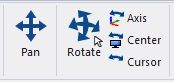
- From the View ribbon tab, click Axis.
- From the Draw or Model ribbon tab, choose Rotate > Rotate Current Axis.
- From the menu bar, click View > Interaction > Rotate Current Axis.
- Right-click in the Modeler window and choose View > Rotate > Rotate Current Axis from the shortcut menu.
- Click and drag the mouse in the direction you want to rotate the view.
- To exit the rotation mode, click the command again (per step 1) or press Esc.
To rotate the view around the Screen Center:
- Choose the Screen Center rotation mode using one of the following four methods:
- From the View ribbon tab, click Center.
- From the Draw or Model ribbon tab, choose Rotate > Rotate Screen Center.
- From the menu bar, click View > Interaction > Rotate Screen Center.
- Right-click in the Modeler window and choose View > Rotate > Rotate Screen Center from the shortcut menu.
- Click and drag the mouse in the direction you want to rotate the view.
- To exit the rotation mode, click the command again (per step 1) or press Esc.
To rotate the view around the Cursor location:
- Choose the Cursor rotation mode using one of the following three methods:
- From the View ribbon tab, click Cursor.
- From the menu bar, click View > Interaction > Rotate Cursor.
- Right-click in the Modeler window and choose View > Rotate > Rotate Cursor from the shortcut menu.
- Click and drag the mouse in the direction you want to rotate the view.
- To exit the rotation mode, click the command again (per step 1) or press Esc.
Spin Mode: This tool is useful for capturing animations (for presentation purposes) that show a 360 degree view of the model geometry, mesh, or simulation results.
To Spin the model view (that is, to keep it rotating after you release the mouse button):
- Choose the Spin mode using one of the following two methods:
- From the Draw or Model ribbon tab, choose Rotate > Spin.
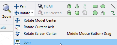
- From the menu bar, click View > Interaction > Spin.
- Click and drag the mouse in the direction you want to spin the view. Release the mouse button while still dragging.
- The model will continue to spin in the specified direction. The spinning speed will be proportional to how fast you were dragging the cursor when you released the mouse button.
- The center of rotation for the Spin mode is controlled by the Default Rotation About option selected in the 3D UI Options dialog box.
- The X, Y, and Z keys also work as modifiers for the Spin mode (for constrained spinning about one of the active coordinate system axes).
- To exit the Spin mode, click the command again (per step 1) or press Esc.

If rotation response is slow, especially for complex models:
- For some graphics cards, you can improve the performance by setting NVIDIA Control Panel > 3D Settings > Manage 3D Settings > Global Settings > Global Presets: Workstation App - Dynamic Streaming.
For more information about graphics cards, see the Open GL section under Installation Prerequisites in the Ansys EM Installation Guide.