Using the Orientation Gadget
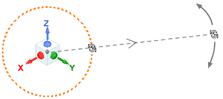
The Orientation Gadget is a tool for quickly manipulating the view orientation of 3D models and 3D plots graphically. It is a convenient alternative to using the Orient drop-down menu on the View ribbon tab. The Orientation Gadget is enabled by default and appears near the lower left corner of the display area in Modeler and 3D Plot windows:
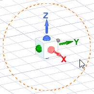
The orange dashed circle appears only when the cursor is near the gadget, and its purpose is discussed later in this topic.
There is a colored dot at the center of each face of the cube and red (X), green (Y), and blue (Z) axes, indicating the axis positive directions for the currently active coordinate system. Additionally, there is a smaller gray dot at the corner where the +X, +Y, and +Z faces meet.
The following list summarizes the results of clicking different parts of the gadget (and optionally dragging the mouse while clicking):
- Click the large dot at the center of any of the six cube faces:
- Click on one of the gadget axes:
- Click the small gray dot at the cube's +X, +Y, +Z corner:
- Click on or very close to the cube (but not on an axis or dot) and drag the mouse:
- X + click and drag to rotate the view orientation about the active X axis.
- Y + click and drag to rotate the view orientation about the active Y axis.
- Z + click and drag to rotate the view orientation about the active Z axis.
- Orange dashed circle:
- Click anywhere on the circle: The model rotates 90 degrees clockwise.
- Ctrl+click anywhere on the circle: The model rotates 90 degrees counterclockwise. This action and the preceding one are particularly useful for changing the in-plane positive axis directions for standard top, bottom, left, right, front, or back views.
- Click and drag: Freely rotates the model in either direction. Release the mouse button when the desired orientation is reached. While the mouse button remains pressed, the cursor changes to a rotation icon:
This action rotates the view orientation to place the side of the model that the clicked face represents towards you, parallel with the screen. For example, if you click the dot on the -Y face, the -Y side of the model faces you, which is the Left view (+Y viewing direction).
If the current viewing direction corresponds to one of the global or active user-defined coordinate system axes (±X/Ux, ±Y/Uy, or ±Z/Uz), clicking the axis label or dot at the center of the Orientation Gadget (on the face that is towards you) reverses the view orientation. So, with a single click of the mouse, you can switch from front-to-back, right-to-left, and top-to-bottom (or the inverses of these view orientation changes).
This action is equivalent to clicking the dot at the center of the same positive cube face. The axis orientation becomes perpendicular to the screen and towards you. Therefore, the resulting three views are looking at the +X (front), +Y (right), or +Z (top) side of the model (-X, -Y, or -Z viewing direction, respectively).
This action produces the standard Isometric view orientation.
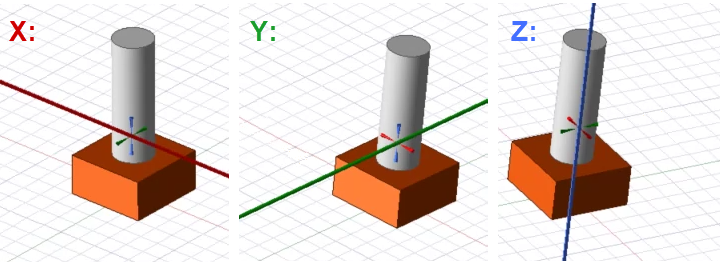
This action freely rotates the view orientation. The rotation center depends on the Default Rotation About option selected in the 3D UI Options dialog box. The behavior is equivalent to clicking and dragging in the display area using the middle button / wheel but is performed with the left mouse button. Additionally, you can constrain rotation to be about any of the three active coordinate system axes by pressing one of the following keys while clicking and dragging the mouse:
During constrained rotation, a heavy red (X), green (Y), or blue (Z) axis line appears in the Modeler window to provide a clear visual indication of the axis of rotation. These axes pass through the center of rotation, and this center is marked by crosshairs. When dragging the view orientation gadget to rotate the view, the center of rotation is the centerpoint of the drawing canvas. The following image shows the appearance of the rotation axes and center markers:
Addtionally, a pair of gold, circular arrows appear on the view orientation gadget indicating the axis of constrained rotation:
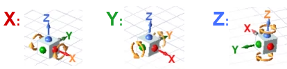
While the same constrained rotation functionality for 3D models is also available for 3D reports, the red, green, and blue axes do not appear in 3D report windows during axis-constrained rotation. However, the pair of circular, gold arrows appear on the view orientation gadget in both the Modeler and 3D Report windows to indicate the axis of constrained rotation.
For more information and tips about the usage of this feature, see Rotating or Spinning the View.
This circle is used to rotate the current view about an axis normal to the screen. That is, the view rotation is constrained to the plane of the screen regardless of the current viewing direction. The line weight of the dashed orange circle becomes heavier when the cursor is touching it, indicating a correct clicking point. There are three actions, as follows:
You do not have to keep the cursor on the circle while dragging. You can often achieve more precise rotations with the cursor further away from the orientation gadget. Moving the cursor in a radial direction away from the center of the orientation gadget produces minimal rotation. Then, move it tangentially for precise rotation. The greater the distance from the gadget, the finer the rotational control.
The appearance of the Orientation Gadget for each of the standard view orientation is as shown in the following image:
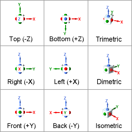
The orientation, colored dots, and axes of the Orientation Gadget correspond to the active coordinate system, whether Global or user-defined. All standard views are defined in the same manner as they are for the global CS, but Ux, Uy, and Uz directions are used instead of global X, Y, and Z.
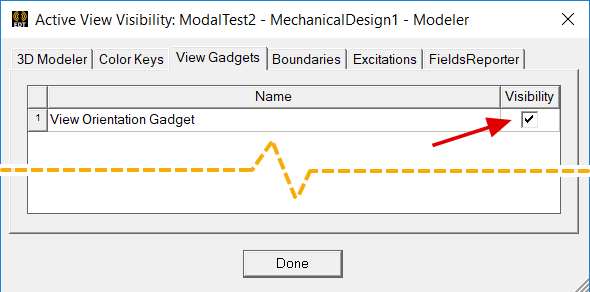
Controlling Visibility of the Orientation Gadget
You can enable or disable the Orientation Gadget visibility as follows:
- Access the Active View Visibility dialog box using one of the following two methods:
- From the menu bar, click View > Visibility > Active View Visibility.
- On the View, Draw, or Model ribbon tab, click
 Hide/Show overlaid visualization in the active view.
 - Select the View Gadgets tab.
- Select or clear the checkbox in the Visibility column to the right of View Orientation Gadget to control the gadget visibility.
- Click Done to close the dialog box.