
Setting HFSS Options
To set HFSS options:
- Click Tools>Options>
General Options to display
the Options dialog box. Select the HFSS
entry in the hierarchical window, and press the + sign to show the choices
under HFSS.
- Under General options, select or clear the following check boxes:

- Save before solving
- Apply variation deletions immediately.
Checking this saves disk space.
- Save Optimetrics Field solutions.
Checking this uses more disk space.
- Under Solution Type, you can set the default solution type when you initially insert a project. Select one of the following from the Default solution type drop-down menu:
- Eigenmode
- Driven Modal
- Driven Terminal
- Transient
- Transient Network
- Driven Modal (Composite Excitation)
- Driven Terminal (Composite Excitation)
- In the Material Options section:
- Check or uncheck whether to Include ferrite materials
- Set the Solve Inside threshold values in Siemens/m.
- In the Boundary Assignment section, select or clear the following check boxes and settings.
When this is checked, the creation of boundaries and excitations use Wizard to guide you through the process. When this is not checked, the creation of boundaries and excitations displays a Properties dialog with tabs for different kinds of information.
- Duplicate boundaries/mesh operations with geometry
When this is checked, you can duplicate a boundary or excitation when its geometry is pasted or duplicated. See Duplicating Boundaries and Excitations with Geometry.
- Visualize Boundaries on geometry.
When this is checked, boundaries on geometries are displayed. Unchecking this turns off boundary visualization, and speeds up the display for complex models.
- Auto assign terminals on ports
When this is checked, the commands to assign wave or lumped ports will automatically assign terminals. See Assigning Wave Ports for Terminal Solutions.
- Automatic PEC creation on wave port. See Assigning Wave Ports for Modal Solutions and Assigning Wave Ports for Terminal Solutions.
In HFSS, A wave port must have 'solve inside' objects on one side only. An internal wave port would require a PEC object to be attached to and cover the opposite side before the solution can proceed. This feature automatically adds a PEC backing to every newly created wave port when necessary.
A dialog for creating wave port PEC backing will show up if the current wave port assignment is not valid. The general rule is that the dialog for creating wave port PEC backing appears if the wave port is internal to the design and does not touch any non-solve-inside component. If a project has open region defined, all geometries are considered internal. A wave port is not valid if these conditions are true:
- the wave port is contained by objects that have maximum volume or FEBI Hybrid region or Radiation boundary (also called internal to the design).
- if a project has open region defined, all geometries are considered internal.
- the wave port does not have a non-solve-inside backing (in this case, does not touch any non-solve-inside object).
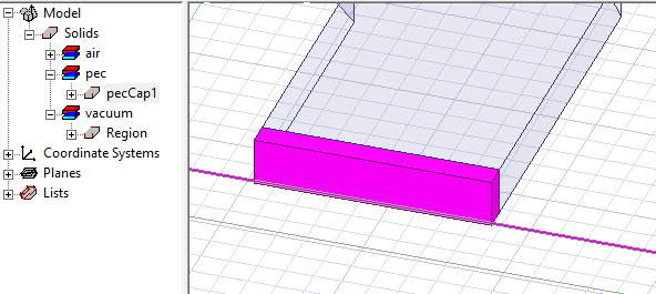
When a new wave port is created and requires a PEC backing, a dialog window opens to let users create such backing by extruding the port face with specified thickness. You have the option to flip the side of the PEC backing. You can also set the thickness as a variable.
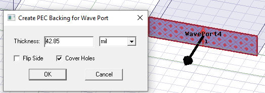
After clicking OK, the PEC backing is created and the new PEC object appears in the History tree.
- In the Post Processing Options section:
- Set the default Matrix sort order. This affects the order of the Matrix Data, and is of interest depending on how port names are assigned for that design. The default is ascending alphanumeric. This can also be a User Specified order that defaults to creation order.