
Setting up a Near-Field Line
To evaluate the near field along a line, set up a near-field line. The near-field line can be a polyline with one or more segments. To plot near-field values along the line, you will select the line object from the Geometry list in the Traces dialog box when you create a report.
- Draw a polyline in post-processing mode.
- Click HFSS >Radiation>Insert Near Field Setup>Line.
The Near Field Line Setup dialog box appears. If the design is Modal/Terminal Solution type the dialogue will include a Radiation Surface tab. If the design is HFSS SBR+ or includes SBR+ Hybrid Regions, the dialogue does not include the Radiation Surface tab because with SBR+ designs, the Radiation surface is defined or selected before simulation using the Field Observation Domain pane in the SBR+ Solution setup Options tab or the Hybrid tab of an HFSS Modal or Terminal setup.
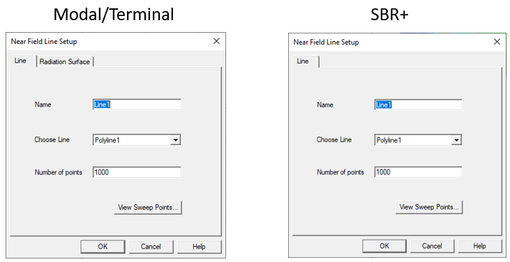
- Under the Near Field Line Setup tab, type a name for the line in the Name text box.
- Select the polyline along which you want to evaluate the near fields from the Choose Line list.
- Specify the Number of points in the line.
This is the total number of equally spaced points on the line. Specifying points on the line will enable you to plot the near-field values across a normalized distance, that is, to create a value versus distance plot of a near-field quantity on the line.
You can click View Sweep Points to view a dialog that lists the points.
- For a Modal or Terminal design, click the Radiation Surface tab.
By default, the Use Boundary Radiation Surfaces radio button is selected.
To specify a surface other than an assigned radiation or PML boundary over which to integrate the radiated fields, you must first create a face list. To create a facelist see Creating a Face List. The face list cannot include a face that lies on a PML object.
If you have created one or more face lists, the Use Custom Radiation Surface radio button is enabled.
- Select Use Custom Radiation Surface.
This enables the Choose from existing face list field.
- Select a defined face list from drop down menu.
HFSS will use the surfaces in the face list as the radiating surfaces when calculating the near fields.
- Click OK.
You must have defined at least one radiation or PML boundary in the design for HFSS to compute near-field quantities, regardless of which radiation surfaces you instruct HFSS to use when calculating the near fields. You do not need to re-solve the problem if you modify radiation surfaces in the Near Field Line Setup window.
For parts of the near-field line lying outside of the model region, near-field approximation is calculated. However, if parts of the line lie inside the model region, the model fields are used to compute interpolated values. A section of the near-field line is considered to overlap the model if it lies in the enlarged model region after accounting for symmetry planes.