
Setting up a Near-Field Box
To evaluate the near field in a box, set up a near-field box. The near-field box is defined length, height, and width parameters, and samples parameters for each dimension. To plot near-field values in the box, you will select the box object from the Geometry list in the Traces dialog box when you create a report.
- Draw a polyline in post-processing mode.
- Click HFSS >Radiation>Insert Near Field Setup>Box.
The Near Field Line Setup dialog box appears. If the design is Modal/Terminal Solution type the dialogue will include a Radiation Surface tab. If the design is HFSS SBR+ or includes SBR+ Hybrid Regions, the dialogue does not include the Radiation Surface tab because with SBR+ designs, the Radiation surface is defined or selected before simulation using the Field Observation Domain pane in the SBR+ Solution setup Options tab or the Hybrid tab of an HFSS Modal or Terminal setup.
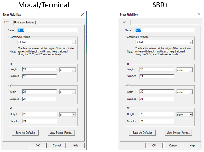
- Type a name for the box in the Name text box.
- Select a Relative Coordinate system to use for the box.
- Specify the Length for the U, V, and W, dimension, the units, and the number of samples.
This defines the box and gives the total number of equally spaced sample points in the box.
- For a Terminal or Modal design, use the Radiation
Surface tab to select the solved surface from which to calculate
radiated fields.
Use Boundary Radiation Surfaces is selected by default, indicating that the radiated fields will be calculated using the assigned radiation or PML surface. For some models you may find it it more efficient and/or accurate to use an interior surface. In this case, select Use Custom Radiation Surface, and choose a face list that you previously created in the modeler.
- Click OK.
You must have defined at least one radiation or PML boundary in the design for HFSS to compute near-field quantities, regardless of which radiation surfaces you instruct HFSS to use when calculating the near fields. You do not need to re-solve the problem if you modify radiation surfaces in the Near Field Box Setup window.
For parts of the near-field box lying outside of the model region, near-field approximation is calculated. However, if parts of the line lie inside the model region, the model fields are used to compute interpolated values. A section of the near-field line is considered to overlap the model if it lies in the enlarged model region after accounting for symmetry planes.