
Moving Faces Along a Vector
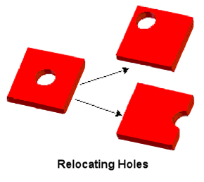
To move the faces of a 3D object a specified distance along a vector use the Modeler> Surface> Move Faces> Along Vector command. Each selected face is moved along the vector, normal to its original plane. The faces that adjoin the original face are extended or shortened along their own planes to meet the new face. Note that the adjoining faces will not be sheared or bent.
This command is useful for relocating holes in an object, as shown below.
To move an object face along a vector:
- Click Select Faces on the shortcut menu.
- Select the face of the object you want to move.
If you have created a suitable face list, right-click the list and click Select Assignment from the shortcut menu. You can operate on faces in the list.
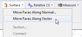
- From the menu bar, click Modeler> Surface> Move Faces> Along Vector, or, on the Draw ribbon tab, click Surface> Move Faces Along Vector:
- Specify the vector along which the face will be moved:
- Select an arbitrary anchor point in one of the following ways:
- Click the point.
- Type the point's coordinates in the X, Y, and Z boxes.
Any point in the drawing region can be selected; however, selecting an anchor point on the object's edge or within the object makes it easier to select the vector.
- Select a second point in one of the following ways:
- Click the point.
- Type the coordinates of a point relative to the anchor point in the dX, dY, and dZ boxes, where d is the distance from the previously selected point.
This point defines the direction and distance from the anchor point to move the face.
The face is moved along the vector you specified.
- Select an arbitrary anchor point in one of the following ways:
To move every face of an object normal to its surface, use the Edit>Arrange>Offset command.