Cable Modeling in HFSS (Beta)
A Beta feature in HFSS lets you can add and edit new cables and harness and solve them within HFSS.
This menu provides access to editors for new and existing cables, editing cable sources, export to and import from libraries, cable harness support, as well as W-element export. The feature lets you create cables and cable bundles, and drag the cables into the bundle. The feature supports straight wire and twisted pair cable. Bundle jacket types include insulation and braided shield. The software automatically generates the cross sections based on a list of conductors and their diameters. This means you have no need to draw complicated geometries. The cable editor supports hierarchy, which enables infinite nesting of bundles within bundles.
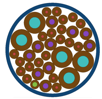
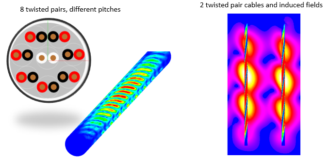
The fields on the cable’s perimeter are radiation sources into the surrounding 3D domain. Fields depend on position, terminal excitations, twisting rates. The software automatically maps the 2D solutions (weighted by position-dependent voltage and currents) to the 3D cable surfaces.
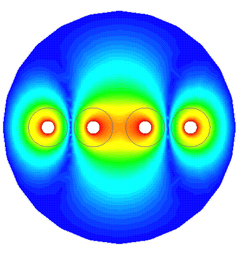
The Cable modeling feature employs a hybrid 2D approach: It generates “samples” of twisted pair cross sections at many locations along the cable. It does 2D solution for RLGC parameters and fields for each cross section. These calculations can be done in parallel. It then uses a semi-analytic transmission line model to compute voltages and currents at any position along the cable length.
You can combine the cable model with additional 3D geometry (for example, a metallic enclosure or the chassis of a vehicle) to see how the fields radiated from the cable interact with surrounding structures. You can also export W-element models of the cable for circuit simulations in Nexxim or HSPICE.
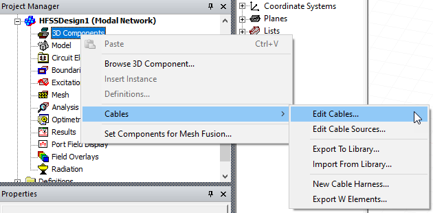
HFSS Cable Modeling Editor Window
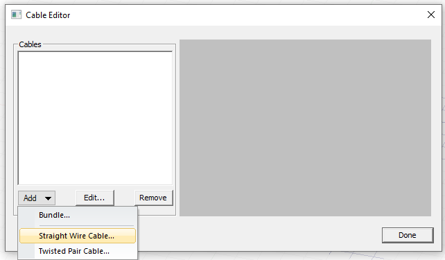
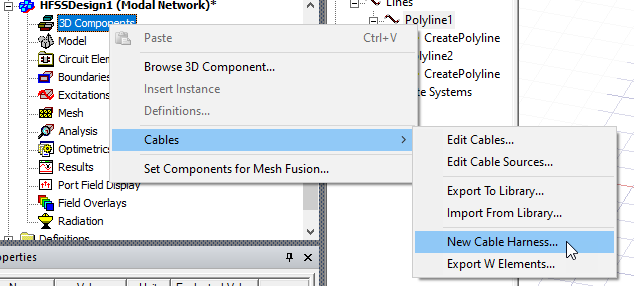
Excecute the Cables>Edit Cables command to open the editor window.
Beginning with a Straight Wire Cable
Though you can build libraries of cables, pairs, bundles and so forth, to begin, first create a Straight Wire Cable..., by selecting from the drop down menu. This opens an editable Property window.
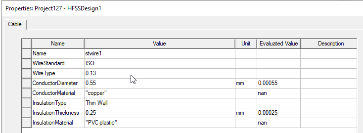
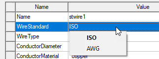
You can edit the properties by typing values or by selecting from drop-down menus for Wire Standard, Wire Type, Insulation Type, or for Conductor or Insulation Material.
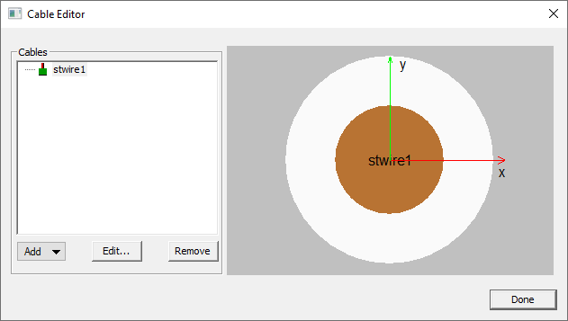
When you have specified the desired name and parameters, OK the Properties dialog box. The Cable Editor shows the current wire.
Adding Twisted Pair Cable
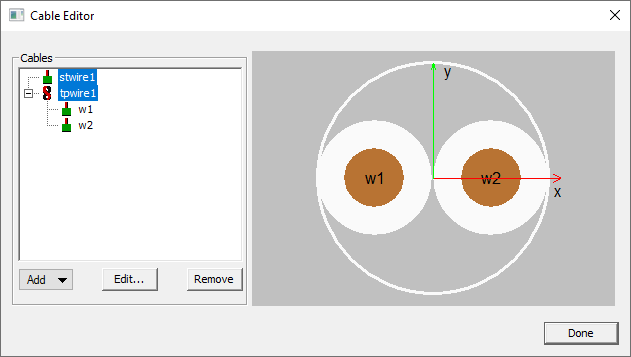
If you then select Add>Twisted Pair Cable..., the Cable Editor shows the result.
Adding Bundles
If you select Add> Bundle..., a Property dialog with tabs for Cable and Shielding opens. The cable editor supports hierarchy, which enables infinite nesting of bundles within bundles.
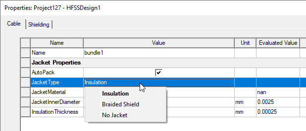
In the Cable tab, you can specify name, whether to AutoPack, select Jacket type from a drop down.
Jacket type can be Insulation, Braided Shield, or No Jacket.
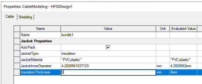
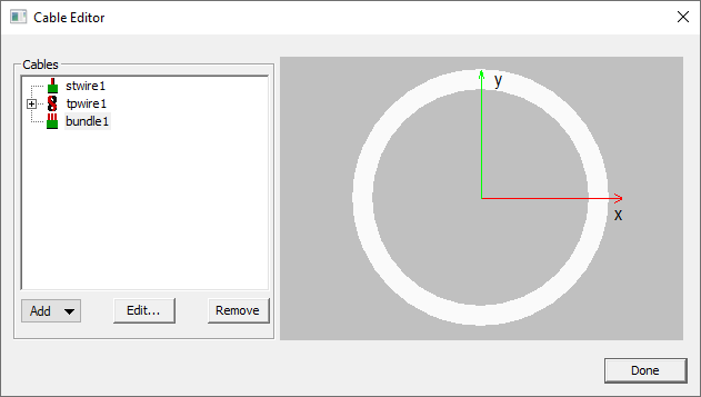
If you select Insulation, the Cable Editor image the bundle will resemble the following:
You then specify Properties for Jacket Material, inner diameter, and insulation thickness:
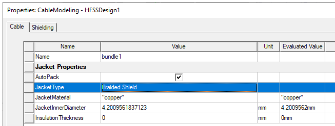
If you select Braided Shield, the Cable Editor image of the bundle will resemble the following:
For details see Technical Notes: Braided Shield Models for Cable Modeling.
For Braided Shield, specify Jacket Material. You cannot edit the inner diameter and insulation thickness.
For Braided Shield, the Shielding tab has a set of parameters:
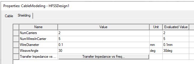
The Number Carriers, NumWiresInCarrier, Wire Diameter and Weave Angle have editable fields. Click Transfer Impedance vs Freq to see the Transfer Impedance Preview:
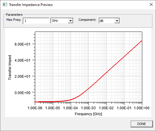
You can Edit the Max Freq value and units, and select Component as dB, Mag, IMag, and Real from the drop down.
If you select No Jacket, the Cable Editor image if the bundle will resemble the following:
For No Jacket, the other properties are not editable.
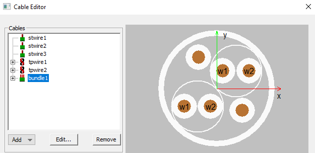
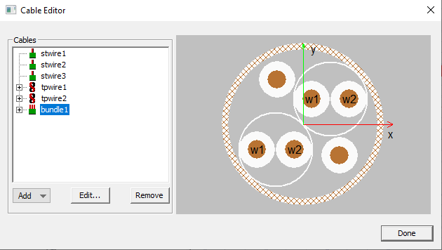
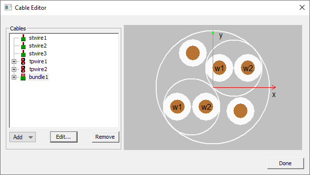
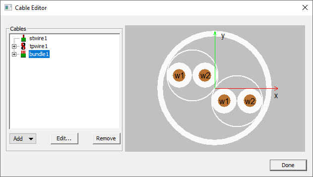
When you click OK for parameters, the dialog box, the currently defined Bundles are listed and the current bundle is shown.
When you drag a wire from the list to the bundle image or to the bundle icon in the Cable tree, an Add Cable to Bundle dialog opens.
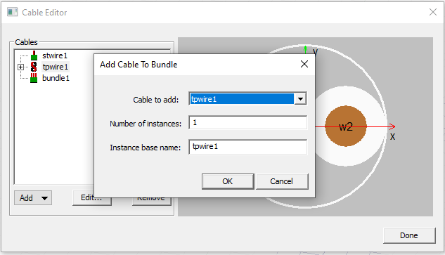
Here you can select the Cable to add, the number of instances, and specify an Instance base name. When you have specified the values for the added cable, and OK the dialog box, the Cable Editor shows the bundle as currently defined, the following example with instances set to 2.
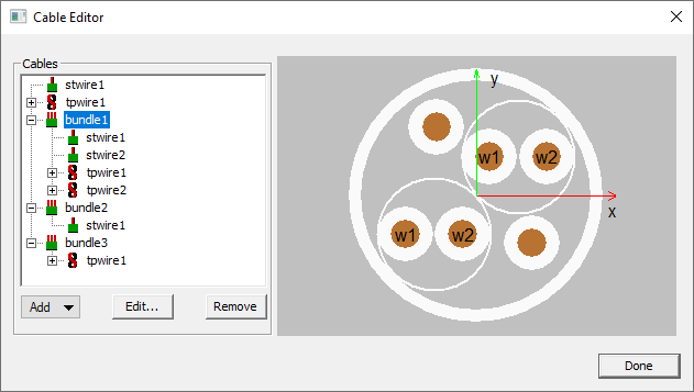
You can define as many bundles as you need, of whatever composition you require.
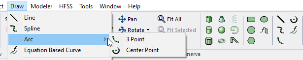
Define Route as Polyline
When you have defined bundles appropriate for your design, the next step is to define a route as a polyline for the cable position in HFSS. The Modeler offers several types of polylines.
Add New Cable Harness
Once you have defined the polyline in the Modeler, go to the Cable Editor, and select Add>New Cable Harness...
This opens the Insert Cable Harness Component dialog box.
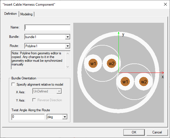
You can use dropdown menus select from bundles you have defined and from polyline routes available in the Modeler.
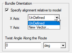
Under Bundle Orientation, you can specify alignment relative to the model. Check Specify alignment relative to model to specify X axis via a New Vector.
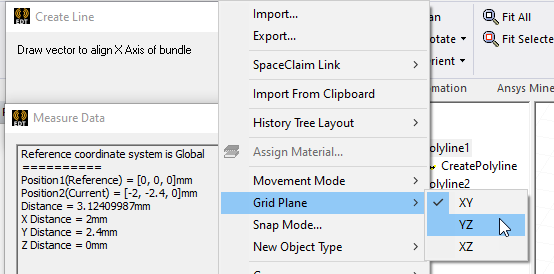
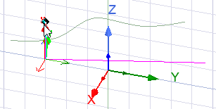
When you select New Vector, remember that you can specify the Grid Plane you use in the Modeler window.
A checkbox lets you Reverse the direction for the Orientation for the Y Axis.
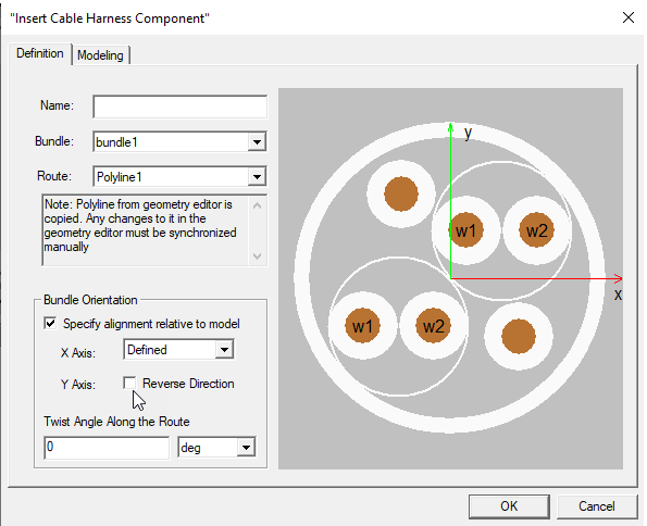
You can also specify Twist Angle Along the Route, selecting units of degrees, degree minutes, degree seconds, or radians from a drop down.
Before selecting the Modeling tab, you must provide a Name.
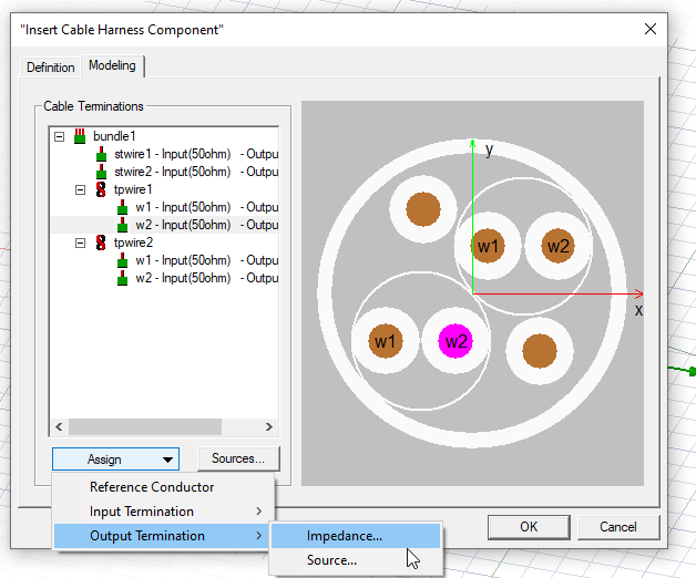
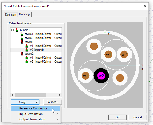
To assign termination impedance, on the Modeling tab, select a conductor wire, either from the list of Cable Terminations, or the clicking on the graphic, and then click Assign>Input Termination> Impedance....
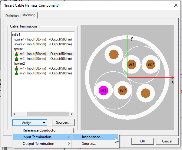
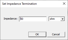
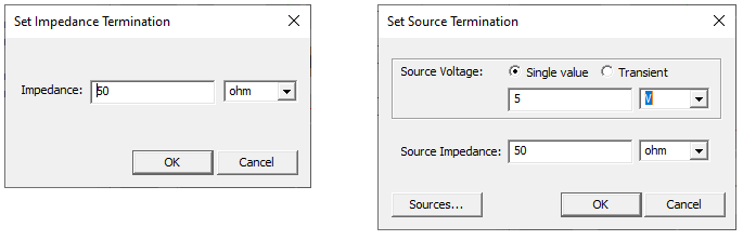
This opens a dialog for you to Set Impedance Termination.
To assign termination source, on the Modeling tab, select a conductor wire, either from the list of Cable Terminations, or the clicking on the graphic, and then click Assign>Input Termination>Source....
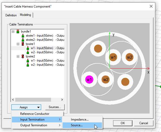
This opens a Set Source Termination dialog.
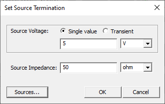
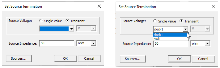
For Single Value, you set source value and units, and source impedance. Selecting Transient changes the fields. If your have not previously defined transient sources, the transient menu is blank, and you can select the Sources... button to open the Cable Time Domain Sources dialog (described below) to define them. If your have previously defined sources, you can select them from the dropdown menu, and specify impedance.
The Output Termination selections work the same way.
The dialogs for Set Impedance Termination and Set Source Termination work the same way.
Selecting Assign>Reference Conductor designates a wire as ground in the list, and visually in the image. Multiple ground references are supported.
Defining and Editing Transient Sources
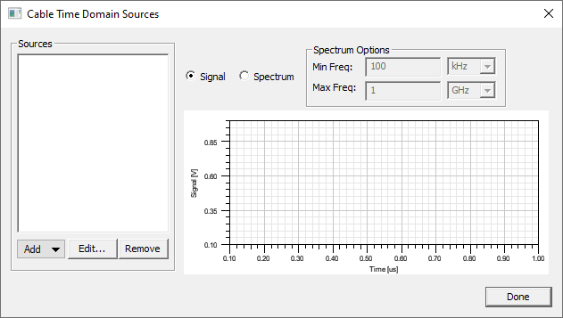
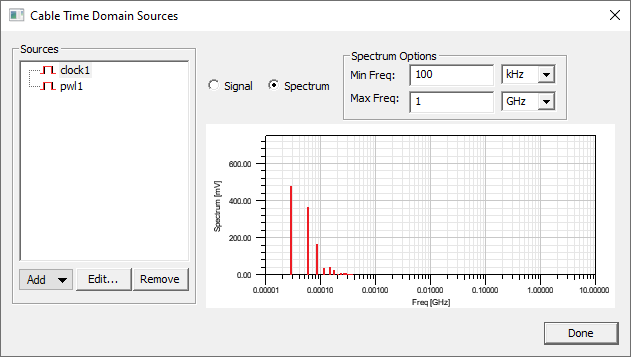
To define transient sources, or to edit previously defined sources, click the Sources... button, either on the Modeling tab Sources... button, or the Sources... button on a Set Source Termination dialog box. This opens the Cable Time Domain Sources dialog box.
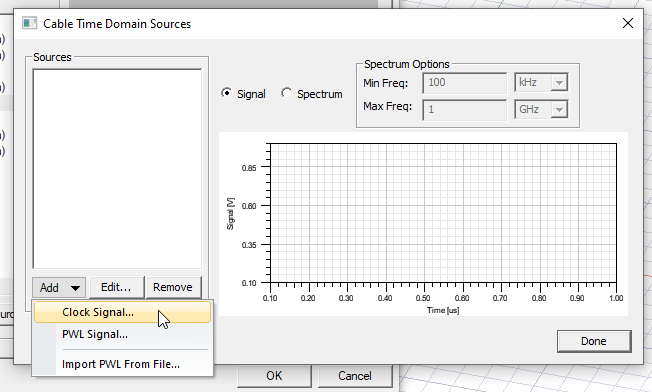
Select the from the Add button dropdown to define a Clock Signal, a PWL Signal, or to Import PWL From File.
Selecting Clock Signal... opens a Properties dialog for the clock signal, and shows the signal graphed as Signal, or Spectrum, based on the parameters you specify.
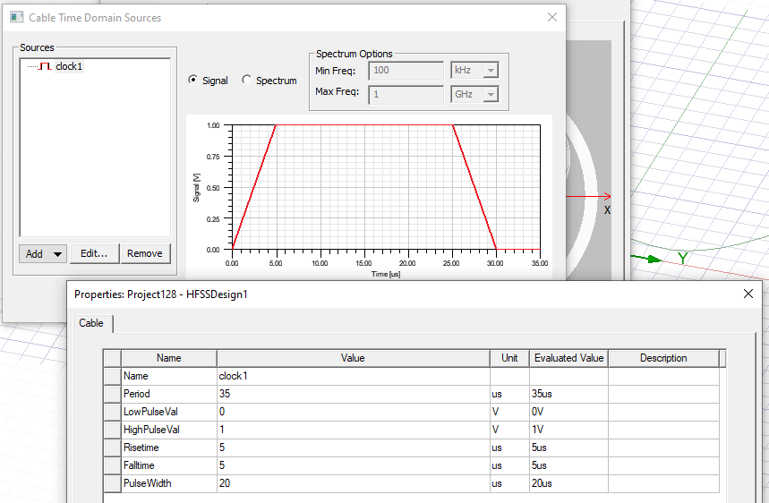
You can provide Name, Period, LowPulseVal, HighPulseVal, Risetime, Falltime, and PulseWith values and units. The units can be variables. When you select OK in the Properties, the clock is displayed and is available to Cable Modeling for selection and editing.
Selecting Add>PWL Signal opens a Properties dialog with a name field and a PWL editor... button.
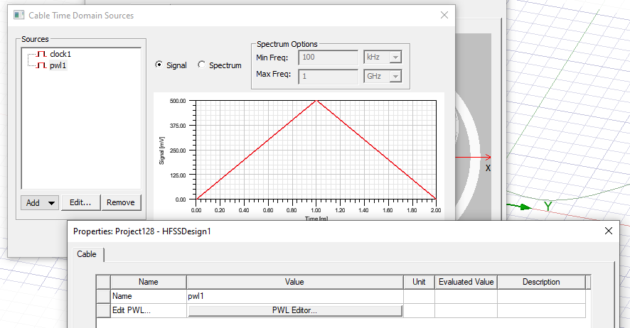
Click the PWL Editor... button to view a text editor that lets you specify PWL parameters as units for time and voltage. Subsequent lines have time and voltage values separated by space or tab.
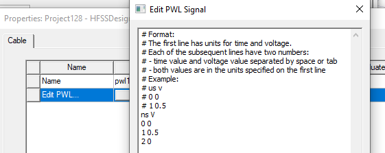
Click OK to accept the parameters from the Edit PWL Signal dialog box, and OK to accept the PWL definition for the Properties dialog.
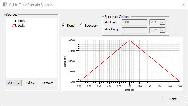
The PWL signal is displayed in the Cable Time Domain Sources dialog and is available for selection and editing.
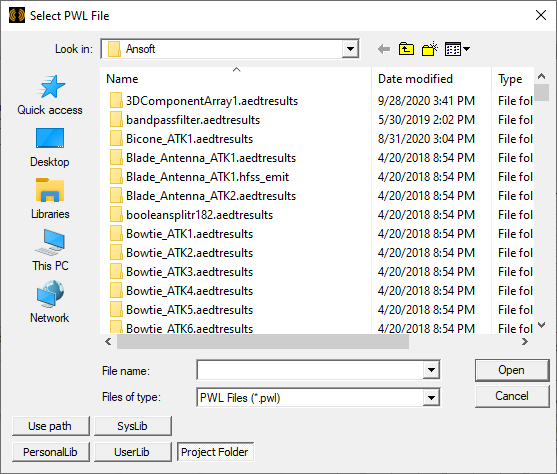
If you select Add> Import PWL From File... a browser opens that lets you navigate to open a plain text file with a .pwl suffix that defines the PWL signal using the same format as the editor.