Assigning PO Region Hybrid Region
While IE Region provides an efficient and accurate alternative to FEM solver for metallic and finite conducting structures, for very electrically large structures it is time consuming and memory demanding. The physical Optics (PO) solver provides first-order scattering information and proves to be efficient approximation for metallic, smooth, locally flat structures. For such geometries for example, a dish reflector, physical optics (PO) can provide an accurate approximation with a significantly reduced computational resource requirement. PO Hybrid Regions are dielectric objects and perfectly conducting objects or sheets solved with physical optics formulation. In light of this, PO Region provides a fast alternative to IE region.
To use PO Region, the solution type must be HFSS with Hybrid and Arrays.
However, because PO is not a full wave solver, we stress that inappropriate use of PO Region may lead to an incorrect solution. PO Region is optimal when the following conditions are satisfied:
- Structure is flat or locally flat, such as a dish reflector;
- Frequency is sufficiently large such that the structure is more than 10 wavelengths in dimension and the structure is sufficiently far away (more than 10 wavelengths) from the radiating source.
- Only a single incident wave excites the PO Region.
- A free standing dielectric IE/PO region cannot touch other free standing IE/PO regions.
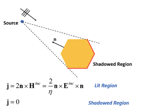
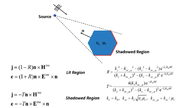
When these conditions are met, a large portion of the
structure is visible to the radiating source. This region is called a
lit region. The remaining region is termed a shadow region. Figure 1
shows visualization of such a concept.
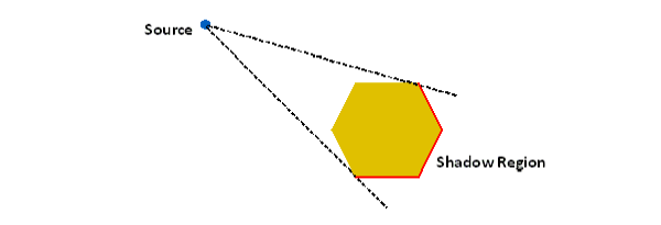
Figure 1 Shadow region of PO solver
In PO approximation, the currents on shadow regions are identically zero. This approximation is acceptable only when frequency is large. In the situation where condition 1) is not met but 2) is satisfied, PO region could still provide reasonable results.
While the accuracy of PO depends on an accurate identification of shadow region, this region is determined based on source location as can be seen from Figure 1. Therefore for the situation where there are multiple sources, shadow regions due to each source could be vastly different. In this situation PO region solver does not provide reliable results. Consequently PO region will only allow a single incident wave direction. Furthermore if there are multiple disjoint FEBI boundaries, the solver will report error message when it detects that a shadow region due to each FEBI box does not mostly overlap. Contact between dielectric PO region and a FE-BI region is allowed.
Note that PO regions may be used together with other useful features like 3D components. For parametric sweeps that vary the distance between assembled 3D components, you can preserve and reuse the component-level meshes between these variations. For example, if a horn and a reflector are defined as 3D components with enabled Do Mesh Assembly option, you can do a placement study running the parametric sweep over the distance between the horn and the antenna, recycling the mesh to speed up the parametric sweep simulations.
The following guidelines summarize the use of PO region.
- Use PO Region when you want a faster solution with sacrifice of accuracy.
- Use PO Region for smooth flat and locally flat structures at the operating frequency.
Note several limitations of the PO region option. First, every conducting material of the metallic PO region will be treated as perfect conductor, and every surface will be treated as PerfE boundary condition disregarding actually assigned materials and boundary conditions. The warning message will be issued if the PO region is assigned on a metal object or a boundary condition that is not a perfect electric conductor. Assigning the PO region to a dielectric object automatically turns this hybrid region to a dielectric PO region. Second, if there are multiple sources modeled with multiple disjoint FE-BI boundaries that makes it hard to accurately define the shadow region, the PO region solver does not provide reliable results. Furthermore, the solver will report an error message when it detects that a shadow region due to each FE-BI region does not mostly overlap.
To Assign a PO Region:
To use PO Region, the solution type must be HFSS with Hybrid and Arrays.
- Select the object you want to assign as an PO Region, and use one of the following menus:
HFSS>Hybrid>Assign Hybrid>PO Region
Right-click in the Modeler window and select Assign Hybrid>PO Region.
Select the Hybrid Regions icon in the Project
tree, right-click, and click Assign>PO
Region.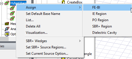
The dialog for Hybrid
Region opens, showing the default name and type selection
as PO Region. Because you may decide to change an assignment for IE Regions,
and PO Regions, the dialog shows these types as radio button selections.
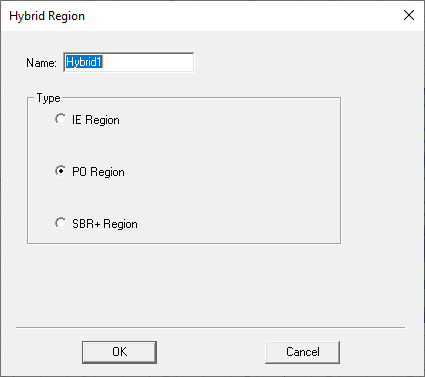
Fig. 2 Hybrid Region dialog for PO region
- When you OK the dialog box, the assignment appears under the Hybrid Regions icon in the Project tree.
Examples of PO Hybrid Simulations
This section looks at three different projects that use PO Hybrid Regions.
Horn Fed Reflector Antenna with PO
An electrically large reflector of 22 wavelengths in diameter is fed with a rectangular horn. To model the system using a hybrid solution with the reflector solved as a PO region, all geometry objects are placed in an HFSS design. The horn geometry is surrounded by an air box named RadiatingSurface. The faces of this object are assigned as hybrid FEBI region, the assignment corresponds to radiation FE-BI boundary in previous versions of Ansys HFSS. To assign, select the air volume surrounding FEM part of a design, and use menu item HFSS > HYBRID> ASSIGN HYBRID > FE-BI. The reflector is modeled as a 2D sheet object with PerfE boundary condition assigned. This sheet object is modeled as a hybrid metallic PO region. To assign, select the reflector and use menu item HFSS > HYBRID > ASSIGN HYBRID > PO REGION. All hybrid regions are listed under the hybrid regions entry in the project manager.
After the solution has completed, standard result reports like field plots, S-parameters and far field characteristics are available. The following figure shows an E-field plot in the FE-BI region assigned to the horn and a J-field plot on the PO region assigned to the reflector dish.
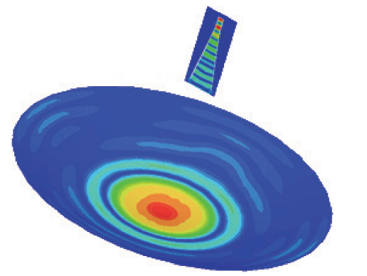
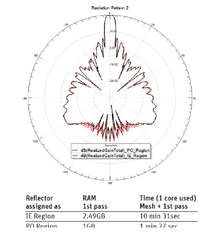
The same geometry was solved with the reflector assigned as an IE region. We can see that the radiation patterns are almost identical and differ only for back lobes, while the PO region option significantly saves computational resources.
Antenna with Raydome using Dielectric PO Hybrid Region
The dielectric PO region option is well suited for simulating antennas covered with radomes. To model the system using the dielectric PO region, all geometry objects are placed in a single HFSS design. Horn geometry is surrounded by the air box that is assigned as a hybrid FE-BI region. The radome geometry should be a standalone 3D object assigned with dielectric material. This object is also assigned as a hybrid dielectric PO region.
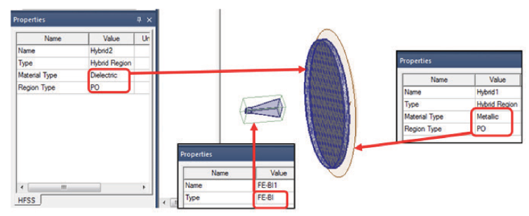
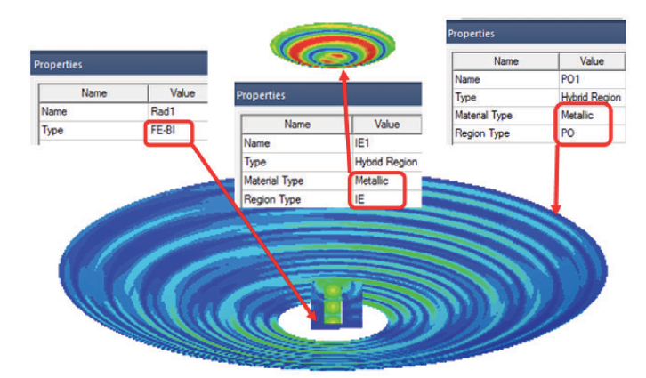
To assign, select the radome and use the menu item HFSS > HYBRID > ASSIGN HYBRID > PO REGION. The dielectric PO region should not touch any other model geometry. This option may be used in the same design together with other hybrid regions. Below is the example of reflector with the flat FR4 radome between the reflector and the horn. Three hybrid regions are assigned: FE-BI for the air box around horn, metallic PO for the PerfE reflector and Dielectric PO for FR4 radome.
Note some limitations for a dielectric PO region: no boundary condition may be assigned on the surface of a dielectric PO region; dielectric PO region cannot touch any other metallic IE or PO regions. However, several touching dielectrics like layers of the radome may be assigned as one hybrid dielectric PO region.
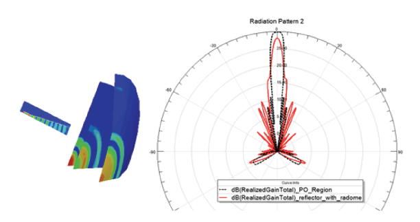
The following figure shows solved fields for a design with three hybrid regions, including, dielectric PO region for FR4 plate radome. Only a quarter of geometry is displayed for a field plot. In the Radiation Pattern plot, the black dotted line represents the far field of the reflector without radome, and the red line refers to the design with FR4 plate between the horn and the reflector.
Cassegrain Reflector: PO and IE Hybrid Regions in One Design
Hybrid PO regions may be combined with IE hybrid regions if desired. For applications like the Cassegrain reflector, there are 2 regions suitable for IE solver: a sub-reflector and a main reflector. A sub-reflector is usually not very large electrically but accuracy of the field solution on the sub-reflector is very important. A main reflector may be electrically very large and smooth making PO approximation justified for the main reflector. Below is the solved field for the Cassegrain system with a relatively small main reflector: The air box around the horn is assigned as a FE-BI region, the sub-reflector is assigned as a metallic IE region and the main reflector is assigned as a metallic PO region.
Technical Notes for Hybrid Regions and PO Solver