Far Field Wave Options
This section describes the panel Far Field Wave Options. Bring up this panel on the Incident Wave Source dialog box as follows.
First click HFSS>Excitations>Assign>Linked Field>Far Field Wave and then, click Next on the Far Field Wave Options tab.
Click Setup Link on the Incident Wave Source dialog to browse for a source project for specifying the linked design.
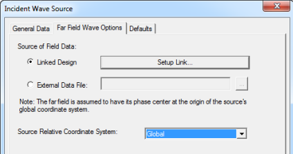
Use a local coordinate system defined in the target design to represent the source origin and rotation relative to target design. All the legacy origin and Euler angles will be translated into local coordinate system.
Legacy Translation of Source Origin Relative to This Design
For legacy projects if the coordinate system you are using in the source design is different from that in the target design, you originally defined the relationship between those coordinate systems as a translation and a rotation. The translation is the offset between the origins of the two coordinate systems, and the rotation was defined through the use of Euler angles.
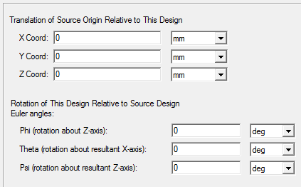
The X-, Y-, and Z-coordinates of the source location and/or Zero Phase Position (the origin for the incident wave) represents the translation of the source design's origin with respect to the target design's origin. For instance, if the source design's origin is located in the target design co-ordinate system at (-2, -2, 1), then the translation between the two coordinate systems is (-2, -2, 1).
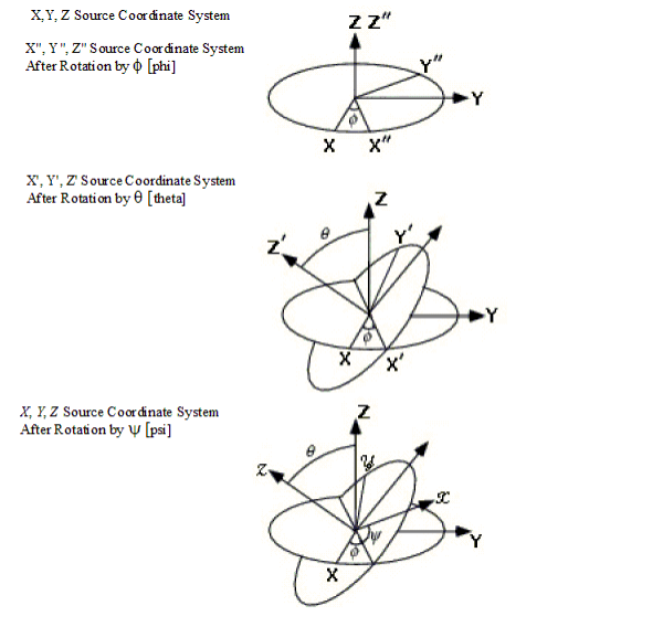
The Euler angles represent the angles through which you can rotate the target design to achieve the desired rotation angles.
All the legacy origin and Euler angles will be translated into local coordinate systems.
A figure that represents the angles and the rotation of a design is at the end of the section.
See Computing Antenna Parameters for a description of how to obtain antenna parameters during post processing.