
Setup Link for Far Field or Near Field Wave
You can access the Setup Link dialog from the Far Field Wave options dialog or Near Field Wave options or from an SBR+ design linked to a Driven Modal antenna.
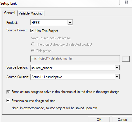
- Select the Edit Link radio button to activate the options in the panel.
- Select the type of the source project (e.g., HFSS, HFSS 3D Layout, SIwave, Maxwell) from
the Product drop-down menu.
Note:
An HFSS-IE project can be used as target or source. Maxwell does not appear in the drop-down menu because it is not applicable for far fields.
- Browse for the source project or check
Use This Project. If you check the
latter option, you must select a source
design from the current project.
Note:
The origin of the global coordinate system of the source project should be in the phase center of the antenna, when you use a Far Field link.
- Specify the Source Solution. The first option in the
Source Solution field is the default.
Note:
The solution in the source design must provide data for the target design's adaptive frequency as well as its sweeps. That is, the adaptive frequency for the target design must be included in the sweep in the source design. If necessary, you can open the source design and add an appropriate frequency point to an existing sweep.
- Use the last two check boxes at the bottom
of the panel as needed.
Note:
Extractor mode means that the software is opened during the link solely for the purpose of solving.
- Under the Variable Mapping tab, you can set the desired variable values in the source design. If the source and target designs contain same named variables, you can choose to Map Variable By Name. In this case, same named variables are mapped automatically.