
Auto Identify Lattice Pair for Coupled Boundaries
Coupled Lattice Pair boundaries enable you to model planes of periodicity where the E-field at every point on the Secondary boundary surface is forced to match the E-field of every corresponding point on the Primary boundary surface to within a phase difference. The transformation used to map the E-field from the Primary to the Secondary is determined by specifying a coordinate system on both the Primary and Secondary boundaries. You can use the Auto Identify Lattice Pair command to auto-set the coordinate system for all surfaces and assign lattice pairs to all faces parallel to the selected plane.
To automatically identify and assign lattice pairs on a selected object:
- Select an object
on which to assign lattice pairs and click HFSS>Boundaries>Assign>Coupled>Auto Assign Lattice Pairto bring up the Auto Identify Lattice Pair
dialog box. Select a plane from the menu.
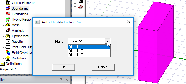
- Click OK.
Lattice Pair boundaries will be assigned to all the pairs of parallel faces which are perpendicular to the selected plane. Each pair is formed by exactly two parallel faces. Notice that in this example two Lattice Pairs appear in the history tree, with the second highlighted in the modeler.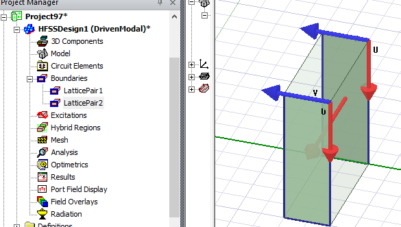
Ansys Electronics Desktop will compute the E-field on this boundary and map it to the secondary boundary using the transformation defined by the Coupled Lattice Pair coordinate systems.