
Assigning Primary Boundaries for a Coupled Lattice Pair
Coupled Lattice Pair boundaries enable you to model planes of periodicity where the E-field at every point on the Secondary boundary surface is forced to match the E-field of every corresponding point on the Primary boundary surface to within a phase difference. The transformation used to map the E-field from the Primary to the Secondary is determined by specifying a coordinate system on both the Primary and Secondary boundaries. You can use the Coupled...>Lattice Pair... command to auto-set the coordinate system, for both Primary and Secondary boundaries together, you have the option of assigning the Primary boundary directly.
To assign a Primary boundary:
- Select a surface
on which to assign the boundary and click HFSS>Boundaries>Assign>Primary
to bring up the Primary Boundary
dialog box.
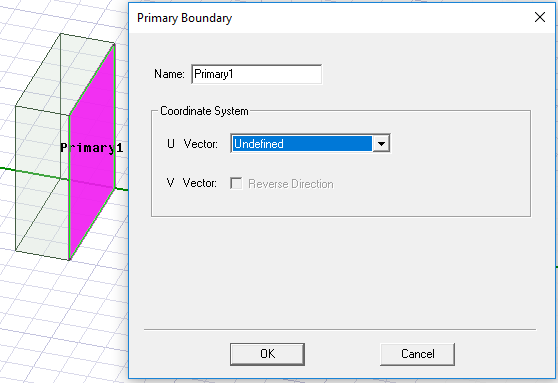
- You must specify the coordinate system in the plane on which the boundary exists. First draw the U vector of the coordinate system. HFSS uses the U vector that you draw and the normal vector of the boundary face to calculate the Vvector. If necessary, you can reverse the direction of the V vector.
- Select New Vector from the U Vector drop-down menu.
The Primary Boundary dialog box disappears while you draw the U vector.
- Select the U vector's origin, which must be on the boundary's surface, either by:
- Clicking the point for the vector origin.
- Typing the point's coordinates in the X, Y, and Z boxes.
- Select a point on the u-axis to indicate the U vector direction.
The Primary Boundary dialog box reappears and the model display shows the U vector and V vector as red and blue arrows respectively.
- If you need to reverse the direction of the V vector, select Reverse Direction.
Ansys Electronics Desktop will compute the E-field on this boundary and map it to the secondary boundary using the transformation defined by the Coupled Lattice Pair coordinate systems.