
Assign Near Field Wave
This section describes the Near Field Wave Options panel on the Incident Wave Source dialog box and how to assign near field waves. The following designs illustrate different ways of using near field sourcing to run a range of analyses on a dish antenna fed by a circular horn antenna.
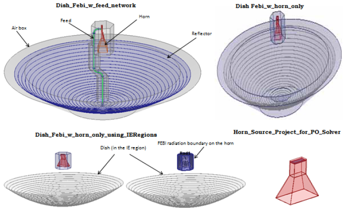
First we will bring up the Near Field Wave Options panel and then, assign Near Field Wave.
- Click HFSS>Excitations>Assign>Linked
Field>Near Field....
The Incident Wave Source dialog box appears.
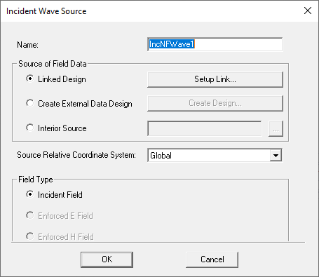
You assign the Excitation name or accept the default.
You can select Linked Design, Create External Data Design, or Interior Source. If you are using a linked design go to step 4.
If you are using an external data file to use to Create External Data Design..., go to Access Near Field External Data Fileand follow the instructions.The dialog supports the choices of E field only and H field only if you select external data.
Do to the nature of the data link, both of these approaches inevitably lose the source design mesh information. Although it might be a reasonable approximation when mesh is complex, in other cases you may want to directly define mesh and near field field, especially when data link source is an external near field design and when source geometry is composed of near field primitives with relatively simple mesh.
HFSS includes an option to add this external near field link as "interior" source. When you select Interior Source you select a data file (.and/.nfd) and HFSS then automates a series of setups, such as near field geometries, mesh operation setup and solution setup, similar to what current Linked Design does. This interior source has the same effect as if its equivalent external near field design is linked to that target design. This interior source also allow relative coordinate system definition. For an example see Example with Interior Source for Near Field Link.
- Click Next
to access the Near Field Wave Options
panel.
Note:
For array problems, the Active option includes the effects of the Near Field in the simulation. To disable the effects, uncheck the Active option.
- Determine whether you want to use a linked
design, an external data file, or an interior source. If you are using
a linked design go to step 4. If you are using an external data
file to use to Create External Data Design...,
go to Access Near Field External Data Fileand follow the
instructions.
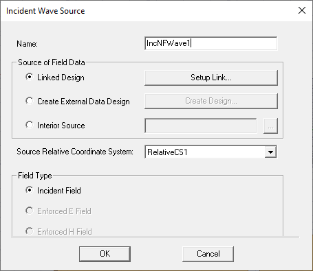
- Click Setup Link on
the Incident Wave Source dialog
to specify the linked design.
Note:
It is through the Setup Link dialog box that you will link the source design to your target design.
- On the Setup Link
dialog box select the radio button Edit
Link.
The fields in the dialog box become active and editable as shown below.
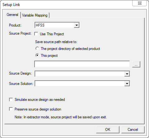
- Select the product
in which you created your source design from the Productdrop-down menu.
Note:
Only HFSS, Maxwell, and SIwave appear in this list.
- Specify the project that has the source
design in one of the following ways:
- Check Use This Project to pick a design from a current working project.
- Click the ellipsis and browse your computer to pick the design.
Note:The option The project directory of selected product points to the default project directory location relative to the product that you selected from the drop-down menu. This is the same project directory that you set on the General Options dialog under Tools> Options. This option is useful especially, when you link across different products. The option This project points to the directory relative to where your current working project is located.
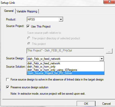
- Pick the source design from the Source Design drop-down menu which lists all the designs in the specified project.
- Pick the setup type from the Source Solution pull-down menu (e.g., Last Adaptive, Sweep).
- Select the last two check boxes as needed
and click OK.
Note:
Go to Simulate source design as needed, for more information about that option.
Preserve source design solution
This is the last option on the Setup Link dialog box. When the source design is closed or it is not included in the project manager window containing the target design, the source design will not be saved. However, if you select this option, which is useful when you are using Maxwell or SIwave the results of the source design is saved.

- Close the Setup
Link dialog, and if necessary, specify the Source Relative
Coordinate System on the Near Field Wave Options
panel of the IncidentWave Source dialog
box.
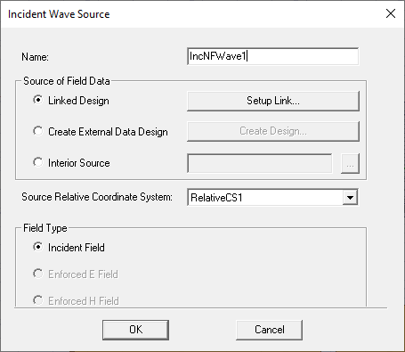
- Click OK to close the dialog. The Near Field wave source point and direction is highlighted in the modeler window, and the wave appears in the Excitations list in the Project.
Simulate source design as needed
Select this option if you modify the source design and you want an updated source design solution to be linked to the target design. If you select this option, make sure that you invalidate the cached link data in the target. To do this, right-click Analysis and select the option Clear Linked Data from the short-cut menu.
