
Access Near Field External Data File
In this section we will show how to access a source of near field which is imposed on a target design through a data file. Instead of using a Linked Design as a source for a near field you can also use data files to impose the near field upon your target project.
For more information about Ansys Near Field Data File (*.and) format see the Ansys Near Field Data File section.
Presupposing that you have prepared the *.and file and associated near field data files:
- Go to HFSS>Excitations>Assign>Linked Field>Near
Field Wave....
The Incident Wave Source:dialog box appears.
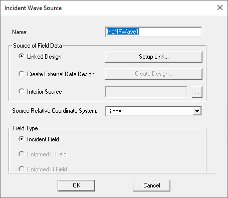
- Select the Create External Data Design radio button to enable the Create Design... button.
- Click Create Design... to browse your computer to
access a previously created *.and file,
which describes the name and location of one or more the near field data
files (*.nfd).
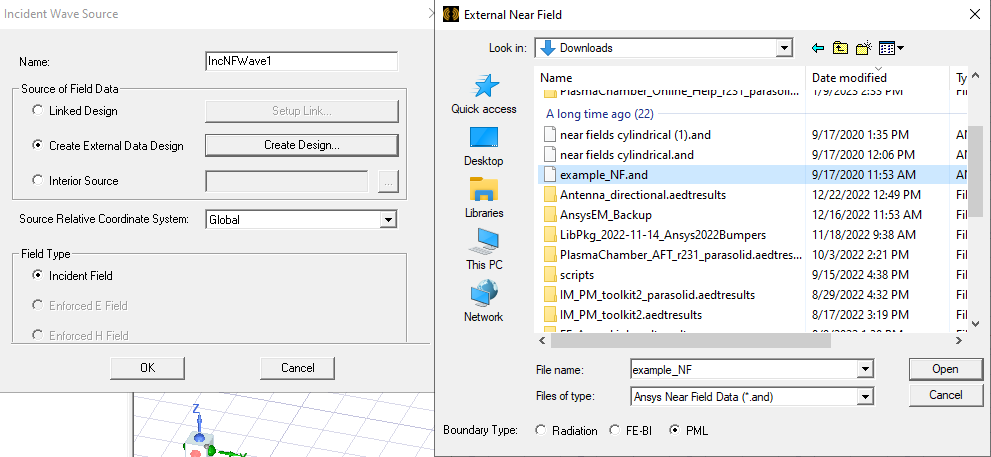
- Select the Boundary Type for the auto-generated design, as Radiation, FE-BI or PML (the default).
- If necessary, specify the Source Relative Coordinate
System on the Near Field Wave Options
panel of the Incident Wave Source dialog box.
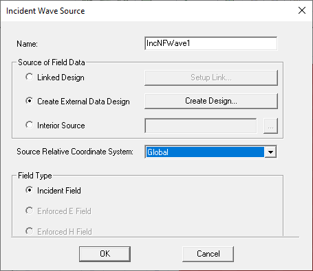
Upon a successful source design generation, the datalink setup for the near field incident wave source will be automatically set to the generated source design.
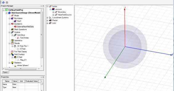
This auto-design generation is neither undo-able nor scriptable. This design becomes the source design for external near field. This workflow allows you to view the external field data via HFSS.
Automatically generated design components include:
- Geometry: the external geometry and a region.
- Boundaries: your choice of Radiation, FE-BI or PML (the default).
- Excitations: an External Near Field Data Excitation. This
is an excitation type for user defined external near field.

The padding ratio is the same as open region.
- For plane case (where "plane" is the geometry specified in the .AND file), it is an open region.
- For all other cases (for other geometries specified in the .AND file), it is auto-open.
Accessing the External Near Field Data Excitation dialog can only be done through the Auto Design under Excitations in Project tree. Other than the Name, no other properties this Excitation are editable through this dialog. It exists to provide you with information about the AND File that was used to create this Auto-Design.
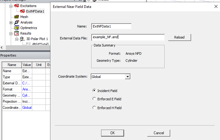
- Analysis:
A default solve setup is created with the adaptive frequency set to the highest frequency in the external data
A discrete frequency sweep is created if multiple frequencies are present in the External Data.
- When you run the Analysis of your target design, it uses this newly created source design for the Near Fields.