


This section lists features which are considered deprecated and their usage is discouraged. These features have usually been replaced by better alternatives and will eventually be removed from the tool in a future release.
Note that if a feature is considered deprecated you will need to explicitly activate it via a tool preference in order to use it.
The generation of structural fault trees from Simulink needs to be activated by clicking Preferences > Diagrams > FTA > Derivation and Generation > Enable generation of fault trees from Simulink.
Note that FTA Generation actions, such as menu entries and editors, are only available if there is a valid medini analyze Simulink package license installed. For more information about licensing, see License Configuration.
Ansys medini analyze supports the automatic generation of fault trees from Simulink models. Starting from a selectable Output port of a Simulink (sub-)system, each path in the model leading to that Output port is traversed. During this navigation for each visited artifact in the Simulink model an FTA pattern is generated. At the end, all these combined patterns from the fault tree give a structural overview of all the inputs which are involved as causes for the selected output. The generation process is parameterizable in order:
to have an influence on the treatment of loops in the model,
to allow the treatment of certain Simulink block types as black boxes to simplify the fault tree and
to affect the FTA diagram generation.
For the selected Output port a scenario node as the top level event is created in the FTA (see figure below). This scenario eventuates either in case the Output port provides a wrong result which is caused by wrong calculation or wrong input signals or in case the container of that Output port fails at all, e.g. by a hardware failure. For both cases events are generated which are connected to the top level event (scenario) by an OR gate.
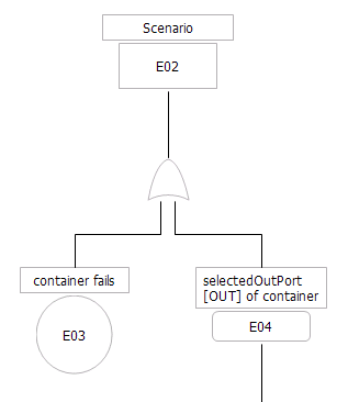
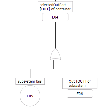
If an Output port is connected to an Output port of a contained block or subsystem then this Output port will fail in case the contained block (or subsystem) fails or the Output port of the contained block provides a wrong signal.
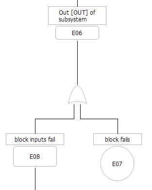
If the contained block or subsystem does not contain any further blocks or subsystems then the Output port connected to that contained block (or subsystem) will fail either when the container fails or its inputs provide wrong signals.
The subtree below the 'inputs fail' event all the involved inputs as events (connected by an OR gate) are listed and how they can fail is shown according to the patterns explained above.
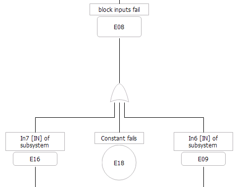
The set of leaf events in the FTA includes all inputs in the same hierarchy level of the selected Output port which contribute to that Output port.
If an event occurs more than once in the generated FTA then it is created only once and for all the other occurrences corresponding transfer gates are created.
In case the underlying Simulink model would cause a loop in the fault tree this loop is prevented by creating an event copy for the already visited Output port which gets the name postfix "+ T" which denotes that this same event occurs a step later in time. After that the navigation through that path of the Simulink model is cancelled. This loop prevention mechanism can be influenced by a parameter which allows to run through a loop more than once.
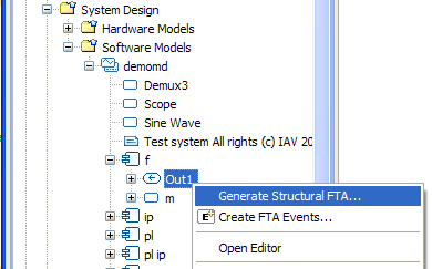
The generation wizard is opened by clicking the corresponding context menu of an Output port of the Simulink model.
The first page in the wizard allows to specify the name of the top level event (scenario node). It is predefined with the name of the Output port. Furthermore the target FTA model has to be determined. Either an existing one can be selected or a new FTA model is created when the 'New Model' button is pressed.

If you want to generate the FTA with the default parameters then press the 'Finish' button and the fault tree is generated into the selected target FTA model and the corresponding diagram will be opened.
On the other hand if you want to parameterize the generation you have to use the next page in the wizard.
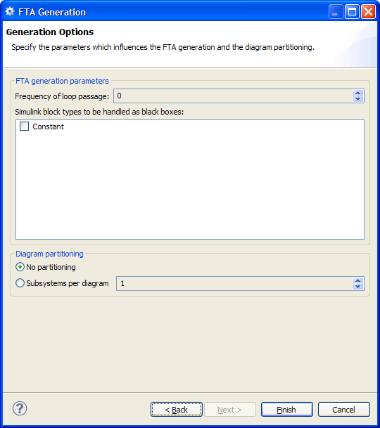
The first option gives you the opportunity to specify how often a loop in the Simulink model is traversed before the navigation of the path is aborted.
In the list box below all available block types of the Simulink model are outlined. If you check a block type this block type is treated as a 'black box' which means that its potential content is not considered for the FTA generation and all its Input ports are not further navigated regardless of the inner structure of this block type.
The last option allows to spread the fault tree over multiple diagrams. If '1' is specified then a new diagram is created whenever the generation algorithm enters a subsystem via one of its Output ports. A larger number will lead to less but bigger diagrams. In case you specified a number but only one diagram is generated then your Simulink model has less (or equal) hierarchy levels in regard to your selected Output port than the number you entered for the diagram partitioning. The generated diagrams are put into a hierarchy which is equivalent to the hierarchy of the Simulink subsystems they have been created for.
In order to open a subdiagram you can either double-click the diagram in the model browser or you open the context menu of an intermediate event in the FTA diagram and choose the 'Open linked diagram' context menu item.
Beginning with release 2022 R2, the integrated solution for Subversion is a legacy feature. The feature will be removed in a future version. Until then, it is disabled by default.
Users are highly encouraged to use an external Subversion client and the CLI integration.