


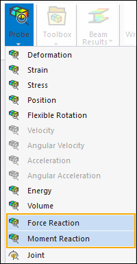
Use the Force Reaction and Moment Reaction probes to do the following:
Create reaction force and moment results for the forces generated at the location of a specific boundary condition, such as fixed supports, displacements, and other constraints.
Determine the forces created at connection locations, such as contact regions, mesh connections, beams, or springs.
During the solution, the application uses the Mechanical APDL OUTRES command to calculate reaction force and moment results. Based on the type of reaction force or moment you specify, boundary condition, contact, etc., the application uses either the RSOL option or the NLOAD and MISC options with the OUTRES command.
The RSOL option calculates nodal constraint reactions. In Mechanical, to calculate nodal reactions, select the Output Controls property . This solution is very accurate but only exists at nodes that are constrained.
The NLOAD and MISC options calculate elemental nodal reactions and elemental miscellaneous data. In Mechanical, to calculate nodal reactions, select the Output Controls property Nodal Forces. This solution exists at the nodes of those elements that support reactions, and the nodes do not need to be constrained. This solution is useful when computing reaction sums on geometric faces and on slices. However, this solution requires a significant amount of disk space and may be less accurate.
Go to a section topic:
Requirements and Limitations
Note the following when working with Force Reaction and Moment Reaction probes:
- Reaction Solution Types for the Mechanical APDL Solver
The Mechanical APDL result file includes two types of reaction solutions:
In Mechanical:
Reaction probes scoped to boundary conditions produce a nodal solution (PRRSOL).
Reaction probes scoped to geometry produce an element-nodal solution (FSUM).
If you compare PRRSOL and FSUM results (or reaction probe results scoped to the same nodes), you may notice slight differences. PRRSOL is typically more accurate.
- Display
For solved reaction probes, the arrow that displays for the probe represents a resultant vector, regardless of the axial direction that you specify in the Result Selection property of the probe. Vector displays in Mechanical always use the Global Coordinate System.
- Analysis Specific
Modal and Harmonic Response analyses do not support Mesh Connections.
For a damped Modal analysis, reaction results provide the By property to compute results based on Mode Number, Phase of Maximum, and Maximum Over Phase.
For a Harmonic Response analysis, reaction results support all options of the result definition available for other harmonic results, and are reported based on the nearest frequency results available: no interpolation is done.
In order to evaluate reactions successfully for a standalone Mode Superposition Harmonic Response analysis that has the Clustering property set to , you need to also make sure that either the Stress, Strain, Nodal, or the General Miscellaneous properties in the Analysis Settings>Output Controls are also set to .
Reaction results sweep through a phase period of 0o and 360o at a specified increment. In previous releases of Mechanical (14.5 and earlier), the default value for this increment was 1o in order to determine the Phase of Maximum and the Maximum Over Phase values. For Harmonic Response analyses only, the phase increment can be controlled using the Phase Increment property. A Phase Increment entry can be between 1o and 10o. The default Phase Increment value is 10o but for legacy database results it is 1o.
Response Spectrum and Random Vibration analyses, the probes do not:
Display arrows.
Support animation.
- Geometry
When you scope this result to geometry, including contact surfaces and cut surfaces, the application calculates the probe using element-nodal data. These calculations are equivalent to those of the FSUM command. That is, the sums for each component direction for the total selected node set and the nodal force and moment contributions of the selected elements attached to the node set.
Recommendation: You should examine your results carefully for geometry scoping. If all elements are selected, the sums of the result are usually zero except where constraints or loads are applied. Element-nodal results for geometry-based scoping should be the same as the node-based results when you specify Boundary Condition as the Location Method if the geometry-based scoping is the same as the boundary condition scoping. However, because of certain limitations associated with how Mechanical calculates scoping, and perhaps based on a model's geometry, the application may produce unexpected element-nodal results.
A reported reaction may be inappropriate if its support shares a face, edge, or vertex with another support, contact pair, or load. This is because the underlying finite element model will have both loads and supports applied to the same nodes.
If a model contains two or more supports that share an edge or vertex, use caution in evaluating the listed reaction forces at those supports. Calculation of reaction forces includes the force acting along bounding edges and vertices. When supports share edges or vertices the global summation of forces may not appear to balance. Reaction forces may be incorrect if they share an edge or face with a contact region.
A limitation exists when the scoping of a probe is applied to a geometric entity (Location Method = ) that shares more than one body. The (unscoped) elements that are adjacent to the scoped body contribute to the probe's results.
- Coordinate System
Force Reaction probes support Cartesian or cylindrical coordinate systems.
Moment Reaction probes support Cartesian coordinate systems only.
For a Static Structural analysis that includes a Cyclic Region object, the application requires that you specify the same coordinate system used by the Cyclic Region for your reaction probe (Orientation property). Reaction probes calculate a preliminary sum using the base sector of the symmetric model in the cylindrical coordinate system of the cyclic analysis. It then multiplies the sum by the number of sectors to obtain the final reaction. Currently, you cannot rotate these final reactions to a different coordinate system.
For Response Spectrum and Random Vibration analyses only, when you set the Location Method to and specify a or a , the application uses the . For any other supported option, such as , the application automatically uses the .
- Connections/Contact
A reaction probe does not solve if it is scoped to a Contact Region that includes a rigid body.
Rigid Dynamics Contact Extraction Behavior: When a Force Reaction probe is scoped to a Contact Region in a Rigid Dynamics analysis and the Extraction property is set to , the probe reports forces acting on the contact surface rather than on the associated rigid body. As a result, the displayed reaction vector represents the contact-side force and appears reversed relative to a force attributed to the rigid body.
Do not support the Location Method option Contact Region when the corresponding Contact Region is scoped to element faces.
For a Moment Reaction scoped to a contact region, the location of the summation point may not be exactly on the contact region itself.
A Moment Reaction probe cannot be scoped to a Grounded Spring.
Since Beam Connections are, by definition, three dimensional in nature, the reactions object scoped to grounded beams may produce reactions in all three directions/axes for two-dimensional analysis. The Tabular Data view will reflect the reactions in all three axes, while the Results view will only reflect values in two axes. The total reactions will be calculated taking into account the reaction components in all three axes.
- Summation Property
For the Moment Reaction probe, the Summation property is available for most Location Method property selections and enables you to select or for your scoped entity. If your selected Location Method does not display this property, the application automatically uses the centroid of the scoped entity for the moment calculation.
Note: When you specify a Moment Reaction probe in a large-scale deformation analysis and you set the Moment Probe Summation Point Offset By Displacements preference (Options > Results) to , the application moves the Summation point to match the closest deformed node to calculate moment arms.
- Surface Location Method
When you set the Location Method property to , you need to specify the following additional properties:
Surface: Select a construction Surface created using the Construction Geometry feature.
Geometry: Select the body or bodies that the construction surface intersects (slices through). Only Body selection is supported.
Extraction: The options for this property depend upon the setting of the Location Method property. See the description for the Extraction property in the Probe Property Descriptions section.
The option of the Location Method property enables you to study reactions on cutting planes. You can extract generated member forces and reactions through a model by using a reaction probe scoped to a Surface object. For this probe type, you must explicitly select the body or bodies (via the Geometry property) to be sliced. You then specify the Extraction property based upon whether you want to study the nodes in front of the plane, behind the plane, or that lie on the specified plane. The Force Reaction probe operates on the elements cut by the plane and only the nodes on those elements that are on the selected by the Extraction property. The application uses a slice algorithm for the option. Because of very slight numerical accuracy issues, such as the number of significant digits used, the algorithm may not capture all expected nodes.
The application can also fail to include a node based on how you slice an element. For example, if a slice plane produces a degenerate polygon, which can happen when a planar shell has only one node in the slice plane, the reaction calculation does not use the node from the element.
For a Moment Reaction probe, when you set the Location Method property to , you must select a body or bodies for the surface to cut. If the Summation property is set to Centroid and you select multiple bodies, the application will use the average the centroids of the bodies for the summation point. The application does not use weighting by volume or by mass for this averaging.
Note: This calculation is different from the calculation used to determine the origin of a coordinate system where geometry consists of multiple bodies.
Important: Do not apply reaction probes to cutting planes that intersect a boundary condition because the reported reactions become unreliable.
Note:Based on the Extraction property setting, the probe uses the nodes of the cut elements, either positive, negative, or that lie on the plane. This requires the application to create certain tolerances along the plane as well as calculated roundoffs of the points. Based on these calculations, the application could produce unexpected results. If the reactions differ significantly, you should modify the location of the Surface plane slightly.
Surfaces used in reaction probes do not currently intersect all geometries, such as line bodies, joints, springs, and MPC contact.
Currently, surface-based probes cannot intersect a plane strain or an axisymmetric model and consequently no results display for this scoping.
- Mesh Connection Location Method
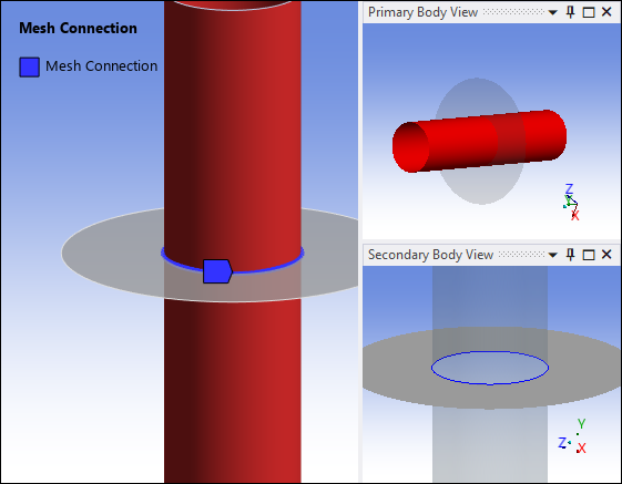
If you specify a Mesh Connection as the reaction type for a probe, make sure you review the scoping of the associated Mesh Connection object. The reaction probe’s evaluation is dependent on this scoping. The color-coding of the Mesh Connection object indicates the scoping of the object. The application displays the primary body’s scoping in red and the secondary geometry’s scoping in blue. The application only uses the color-coded nodes to define the mesh connection and therefore the calculation of the probe result value.
Using the Mesh Connection illustrated below as an example, the application only uses the nodes, and therefore only those elements, of the secondary edge-based (blue) geometry as compared to all of the nodes and elements of the primary face-based (red) geometry. The application excludes the translucent portion of the body associated with the edge scoping when evaluating the result. You must consider whether this impacts your desired objective.
See the Mesh Connections section in the Meshing User’s Guide for more information about creating a Mesh Connection.
- Extraction Property
If you set Extraction equal to Contact (Underlying Element) or Target (Underlying Element) in the Details of either a Force Reaction or Moment Reaction probe, the reaction calculations work by summing the internal forces on the underlying elements under a contact region. These probes can also extract reaction data from surface effect elements. The application creates surface effect elements during the solution process to simulate loads, such as pressures. However, the application does not currently display surface effect elements from the Mesh object or the Connections object.
Therefore, a reported reaction may be inappropriate on a contact face if that face shares topology with another contact face/edge or external load (such as a force or fixed support), which would contribute to the underlying elements' internal force balance. In addition, during a Transient analysis, inertial and damping forces are also included. Another possible scenario could arise for MPC contact of solid surfaces. In this case, if a gap is detected, the solver may build constraints on an additional layer into the solid mesh from the TARGET elements. This produces a more accurate response but will invalidate any reactions from the underlying solid elements of the TARGET elements. If symmetric contact is chosen, be careful to verify which side becomes active for the TARGET elements so that the correct reaction can be determined.
When scoping Force Reaction or Moment Reaction probes to geometry, it is possible that there may be elements (and as a result, element-based reactions) that are currently unavailable for summing purposes. For example, you scope a pressure to a face on your geometry. The solution process also applies surface effect elements to the same face to simulate the pressure loading. The probes, scoped to geometry, currently cannot extract reaction data from the surface effect elements and therefore, in the case of this example, only the underlying solid/shell/line elements of the original mesh contribute reaction data to the probe results.
If mesh elements overlap, reaction probes scoped using the Geometry Selection method may produce unexpected or unreliable results. Select the Mesh object to examine whether elements from one body cross an edge and overlay elements of other bodies.
Defining Reaction Probes
Insert a reaction probe from the Probe drop-down menu on the Solution Context tab. You can also use the context (right-click) menu from an appropriate object or from within the Geometry window.
Specify the Location Method property, as shown below, based on the reaction to solve. The available options depend upon the type of analysis you are performing, and they have associated requirements.
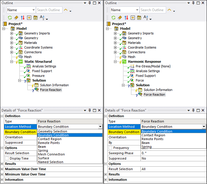
For the selected reaction, use the associated property that displays to select the location of the reaction force, such as a boundary condition, as shown in the following example.
Specify the setting of the additional properties as needed. See the Probe Object Property Descriptions section for a complete description of all properties.
Specify the settings of the Output Controls (Analysis Settings) based on your analysis and reaction type. See the Location Method property Options and Output Controls Requirements topic below for the specific requirements.
Evaluate probe result.
Displaying Reaction Results
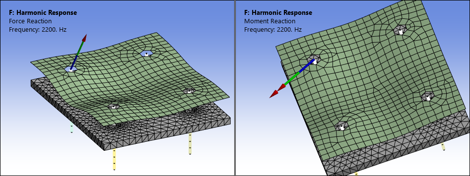
When evaluated, Force Reaction probes automatically display an arrow with a single arrowhead that graphically represents the sum of the reaction vectors. The Moment Reaction probe displays an arrow with a double arrowhead to represent the reaction vector. In general, the application anchors these directional displays at the geometric center or centroid of the nodes included in the scoping.
In the following example, the Force Reaction centroid is at the center of a face scoped to a Fixed Support and the Moment Reaction, also specified using a Fixed Support, uses the setting of the Summation property.
- Considerations
For geometric scoping, the location of the Force Reaction probe is usually the node nearest to the centroid of the scoping.
The location of Moment Reaction probe is usually the Summation Point (the anchor for the moment arm calculation). For non-geometric scoping, there can be exceptions, such as remote points. In this instance, the coordinate (x,y,z) of the remote point becomes the location of the arrowheads.
The magnitude for the probes is based on the sum of the forces or moments.
- Graph and Tabular Data
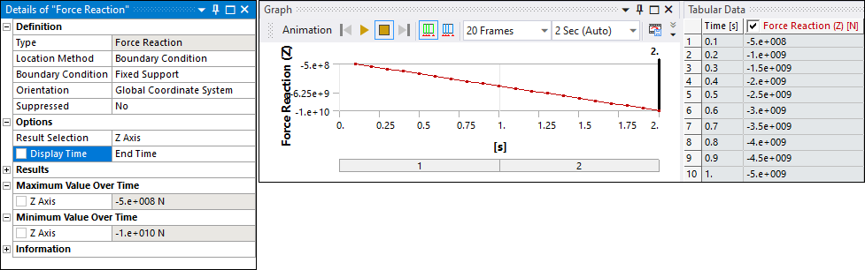
For Static and Transient analyses, the Graph and Tabular Data windows display the history of the reactions/moments. The arrowhead is representative of the specified Display Time.
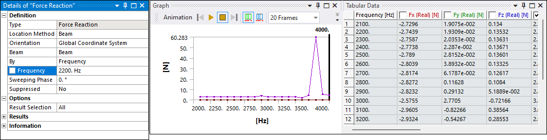
For Harmonic and Modal, the Graph and Tabular Data windows display the reactions/moments for all frequencies/modes in the file. The arrowhead is representative of the specified Frequency/Mode.
Location Method property Options and Output Controls Requirements
Based on the reaction types you select, the following topics outline whether or not you need to activate the Calculate Reactions and/or the Nodal Forces properties for your selected analysis type. Note that there are instances when the default setting for these properties is the active state. Also included are any scoping requirements, recommendations, and/or limitations when defining the various reaction types. Make sure you review this content in addition to the information in Support Requirements and Limitations.
- Boundary Conditions
When you set the Location Method property to , a Boundary Condition property displays. The Boundary Condition property supports the following conditions:
Fixed Support (Face, Edge, and Vertex Rotations (do not include Force Reactions)
Displacements (Face, Edge, and Vertex selections)
Cylindrical Support
Frictionless (Face selection)
Simply Supported (Edge and Vertex selection)
Nodal Displacement
Nodal Rotation
Remote Displacement
Based on your selection, and the analysis type, set the following Output Controls.
Analysis Type Output Controls Requirement Static Structural/Transient Structural
NA
Modal
Set the Calculate Reactions property to .
Harmonic Response – Full
Harmonic Response - Mode-Superposition
If results are expanded from a modal solution, set the Calculate Reactions property to and the Nodal Forces property to either or .
Recommendation: Ansys recommends that you use the option, as the results file size will be smaller and the process time shorter.
Otherwise, set the Calculate Reactions property to .
Important: Force and Moment Reaction probes cannot be evaluated when you specify damping in combination with setting the Expand Results From property set to either or . Review the MXPAND command in the Mechanical APDL Command Reference for additional information about this limitation.
Transient - Mode-Superposition
Response Spectrum
In the upstream Modal analysis, under the Analysis Settings > Output Controls , you must set the Nodal Forces property to either or and set the Store Modal Results property to or .
Recommendation: Ansys recommends that you use the Constrained Nodes option, as the results file size will be smaller and the process time shorter.
Random Vibration
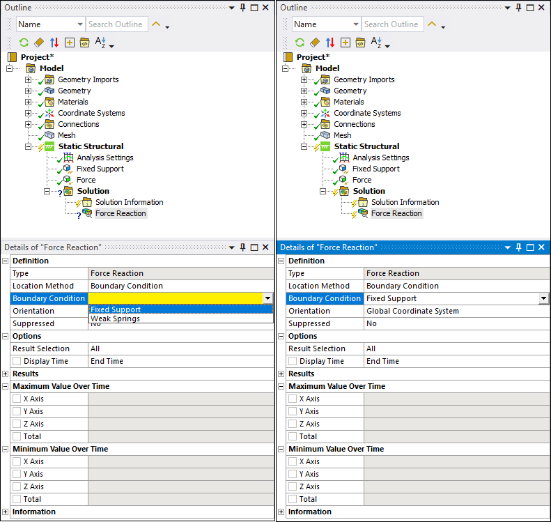
Note: The following additional Boundary Condition property options may be available only in Static Structural and Transient Structural analyses:
: Instructs the solver to include the effects of weak springs in the reaction force calculation. The application only supports this option for the Force Reaction probe and requires you to set the Weak Spring property (Solver Controls > Analysis Settings) to . For an under-constrained model, weak springs automatically stabilize the system.
Compression Only Support: This support does not have any Output Controls requirements. However, reaction probes scoped to a Compression Only Support cannot display results if the solver does not converge.
Elastic Support: Set the Nodal Forces property to .
- Geometry Selection
When you set the Location Method property to , the Geometry property displays. Use selection filters to pick geometry, click in the Geometry field, then click Apply. Supported geometric and mesh entities include Face, Edge, Vertex, Nodes, and Element Faces.
The application only supports geometry selections for Static Structural and Transient Structural analyses. For these analysis types, set the Nodal Forces property to .
Important: If you scope a Force Reaction or Moment Reaction probe to a geometric entity that shares more than one body, the adjacent elements not included in the geometric/mesh scoping contribute to the probe's results.
- Contact Region
When you set the Location Method property to , the Contact Region property displays. Use this property to select a desired Contact Region from the drop-down list. Based on your analysis type, set the following Output Controls.
Analysis Type Output Controls Requirement Static Structural
Nodal Forces property to .
Contact Miscellaneous property to .
General Miscellaneous property to .
Transient Structural
These analysis types do not support contact reactions using the contact element option. They only support contact reactions using the underlying element option. You control the underlying element options by setting the Nodal Forces property to .
Modal
Harmonic Response – Full/MSUP
Harmonic Response Analysis Linked to Modal Analysis
Transient Structural - Linked to Modal Analysis
Important: Your analysis will not solve if the probe is scoped to a Contact Region that includes a rigid body.
- Remote Points
When you set the Location Method property to , a Remote Points property displays. Use this property to select a predefined Remote Point from the drop-down list. Based on your analysis type, set the following Output Controls.
Analysis Type Output Controls Requirement Static Structural/Transient Structural
NA
Modal
Set the Calculate Reactions property to .
Harmonic Response – Full
Harmonic Response - Mode-Superposition
If results are expanded from a modal solution, set the Calculate Reactions property to and the Nodal Forces property to either or .
Recommendation: Ansys recommends that you use the option, as the results file size will be smaller and the process time shorter.
Otherwise, set the Calculate Reactions property to .
Important: Force and Moment Reaction probes cannot be evaluated when you specify damping in combination with setting the Expand Results From property set to either or . Review the MXPAND command in the Mechanical APDL Command Reference for additional information about this limitation.
Transient - Mode-Superposition
Response Spectrum
In the upstream Modal analysis, under the Analysis Settings > Output Controls , you must set the Nodal Forces property to either or and set the Store Modal Results property to or .
Recommendation: Ansys recommends that you use the Constrained Nodes option, as the results file size will be smaller and the process time shorter.
Random Vibration
- Beam
When you set the Location Method property to Beam, a Beam property displays. Use this property to select a predefined Beam from the drop-down list. Based on the beam type and analysis type, set the following Output Controls.
- Body-Ground Beam
Analysis Type Output Controls Requirement Static Structural/Transient Structural
NA
Modal
Set the Calculate Reactions property to .
Harmonic Response – Full
Harmonic Response - Mode-Superposition
If results are expanded from a modal solution, set the Calculate Reactions property to and the Nodal Forces property to either or .
Recommendation: Ansys recommends that you use the option, as the results file size will be smaller and the process time shorter.
Otherwise, set the Calculate Reactions property to .
Important: Force and Moment Reaction probes cannot be evaluated when you specify damping in combination with setting the Expand Results From property set to either or . Review the MXPAND command in the Mechanical APDL Command Reference for additional information about this limitation.
Transient - Mode-Superposition
Response Spectrum
In the upstream Modal analysis, under the Analysis Settings > Output Controls , you must set the Nodal Forces property to either or and set the Store Modal Results property to or .
Recommendation: Ansys recommends that you use the Constrained Nodes option, as the results file size will be smaller and the process time shorter.
Random Vibration
- Body-Body Beam
Analysis Type Output Controls Requirement Static Structural/Transient Structural
NA
Modal
Set the Calculate Reactions property to and the Nodal Forces property to either or .
Note: For a Modal, Harmonic Response, or MSUP analyses, you also need to set the On Demand Expansion Option property (Analysis Settings > Options) to .
Harmonic Response Full/MSUP
Transient Structural Full/MSUP
- Spring (Body-Ground Only)
When you set the Location Method property to , a Spring property displays. Use this property to select a predefined from the drop-down list. Based on the analysis type, set the following Output Controls.
Analysis Type Output Controls Requirement Static Structural/Transient Structural
NA
Modal
Set the Calculate Reactions property to .
Harmonic Response – Full
Harmonic Response - Mode-Superposition
If results are expanded from a modal solution, set the Calculate Reactions property to and the Nodal Forces property to either or .
Recommendation: Ansys recommends that you use the option, as the results file size will be smaller and the process time shorter.
Otherwise, set the Calculate Reactions property to .
Important: Force and Moment Reaction probes cannot be evaluated when you specify damping in combination with setting the Expand Results From property set to either or . Review the MXPAND command in the Mechanical APDL Command Reference for additional information about this limitation.
Transient - Mode-Superposition
Response Spectrum
In the upstream Modal analysis, under the Analysis Settings > Output Controls , you must set the Nodal Forces property to either or and set the Store Modal Results property to or .
Recommendation: Ansys recommends that you use the Constrained Nodes option, as the results file size will be smaller and the process time shorter.
Random Vibration
- Mesh Connection
When you set the Location Method property to , a property displays. Use this property to select a predefined Mesh Connection from the drop-down list.
This Location Method setting is supported by Modal, Static Structural, and Transient Structural, both Full and MSUP, analyses. For all analysis types, set the Nodal Forces property to .
- Surface
When you set the Location Method property to , a Surface property displays. Use this property to select a predefined Surface construction body from the drop-down list. Review the Surface Location Method topic under Requirements and Limitations for more information.
This Location Method setting is supported by Static Structural and Transient Structural, both Full and MSUP, analyses. For all analysis types, set the Nodal Forces property to .
- Named Selection
When you set the Location Method property to , a Named Selection property displays. Use this property to select a predefined Named Selection from the drop-down list. This Location Method setting is supported by Static Structural and Transient Structural (Full) analyses. For each analysis type, set the Nodal Forces property to .
Large Scale Deformation for Moment Reactions
- Large Deflection On - Nodes Offset
When you specify a Moment Reaction probe in a large-scale deformation analysis (Large Deflection property set to ), the application uses the displaced mesh when calculating moment arms for moment probes, as defined by:

Where Sx, Sy, and Sz represent the settings of the Summation property; X, Y, and Z denote the nodal locations; and Ux, Uy, and Uz are the displacements at those node locations.
Important:- Large Deflection On - Summation Point Offset
When you specify a Moment Reaction probe in a large-scale deformation analysis (Large Deflection property set to ) and you set the Moment Probe Summation Point Offset By Displacements preference (Options > Results) to , the application moves the Summation point to match the closest deformed node to calculate moment arms.

Where:
Nx, Ny, and Nz represent the location of the node nearest to x, y, and z.
dx, dy, and dz represent the displacements of that nearest node.
- Large Deflection Off
When the Large Deflection property set to , the displacements are not used in the moment arm calculation, as defined by:

Rigid Dynamics Solver
For the Rigid Dynamics solver, when force or moment reaction probes use Contact Region for the Location Method, it allows you to display the resulting contact forces on a specific contact region. The contact region can be picked using the Contact Region drop-down menu. The Contact Force menu allows you to display either the Total force, the Normal, or the Tangent force. By definition, frictionless contact always reports a normal force and the tangent force reports zero for all components.
Note: Contact regions between the same pair of parts are merged into a single contact region. Consequently, the probes will report the same values for the entire contact region.