To accurately capture the interaction between contact surfaces, it is important that the contact and target sides of the contact region are designated properly. They can be assigned automatically by the application or manually, by scoping. Follow these points when designating the contact or target side:
When bodies with significantly different mesh sizing come into contact, the surface with the finer mesh should be the contact side.
When bodies with different shapes come into contact, assign the concave shape to be the contact side and the flat or convex shape as the target. Similarly, when an edge or corner is in contact with a flat surface, the edge or corner must be the contact side and the flat surface must be the target.
When bodies of differing size come into contact, the larger surface should be the target.
If two bodies with different material properties come into contact, designate the softer one as the contact side and the stiffer one as the target side.
The contact and target can have different geometry types, but each side's geometry type must be consistent. For example, you can't have a single contact side that is a mix of faces from 3D solid elements and edges from 2D shell elements in the same contact definition. The contact surface has to be consistently defined as either a collection of faces, a collection of edges, and so on. See Possible Scoping Combinations.
The contact side (also called the source) is considered in contact with the target (receiving the impact) when a contact's detection point collides with or touches the target surface.
Definitions of all properties/options under Scope are described in detail in the Contact Region object reference description: Scope.
Additional topics include:
| Possible Scoping Combinations |
| Defining Target Surface for Shells |
| Contact and Target Body Views |
| Stiffness Behavior Considerations |
| Flipping Contact and Target Scope Settings |
Possible Scoping Combinations
The following table lists the possible geometry scoping combinations and the Mechanical APDL element types used.
| Scoped Geometry for Contact |
Face
Contact Side |
Edge
Contact Side |
Vertex Contact Side | ||||||||
|
Face
Target Side |
Symmetric pair can be formed |
|
| ||||||||
| Edge Target Side |
|
Symmetric pair can be formed |
| ||||||||
|
Vertex
Target Side | A vertex cannot be designated as the target side of a contact pair. | ||||||||||
Note that:
A line edge can never be designated as the target side of a contact pair.
A vertex can never be designated as the target side of a contact pair.
A vertex can be designated as the contact side on line bodies only.
Defining Target Surface for Shells
To define which face of a shell or surface body will act as the target in a contact pair, use the Target Shell Face property. This is especially important when modeling shell elements, which have distinct top and bottom faces due to their mid-surface-based formulation. The main purpose is to control contact behavior by specifying which face of the shell body should participate in the contact interaction. This helps ensure accurate simulation of physical contact, especially in layered or thin-walled structures. This is important because:
Shell elements represent surfaces with thickness, and contact can occur on either side.
By specifying , , or , you can model realistic contact scenarios, such as:
Contact between two shell bodies.
Contact between a shell and a solid body.
Contact on both sides of a shell.
Typical use cases for this property’s options include:
or : Used when contact is expected only on one side of the shell.
: Useful when contact may occur on either/both sides, but you want to define the contact using a single set of target elements.
: The application decides based on geometry and contact definitions (not valid for nonlinear contact types).
Contact and Target Body Views
The screenshot shows how contact regions are displayed for a model of a break pad (contact in red) and disk (target in blue). The contact and target bodies are displayed as they exist in the assembly in the geometry window. The Body Views on the right show the contact and target bodies isolated without the other bodies in the assembly. This is extremely useful for large assemblies and for visualizing parts in contact that are internal to the structure. This is the default display when you select a Contact Region object.
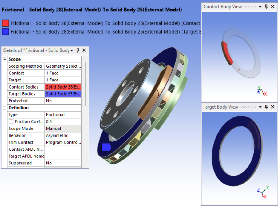
The Body Views feature is available for joint, contact, spring, and beam connections.
Stiffness Behavior Considerations
Keep in mind the following considerations:
The Stiffness Behavior of geometric entities on the contact side can differ from that on the target side, but they must be uniform within each side.
If the Stiffness Behavior is , you must set the definition Behavior to Asymmetric.
You cannot scope the target side in a contact pair to more than one rigid body.
If you have both rigid and flexible bodies in your contact pair, you must scope the rigid body as a target.
For the Mechanical APDL solver, you cannot scope the target side of a contact pair to the edge of a rigid body.
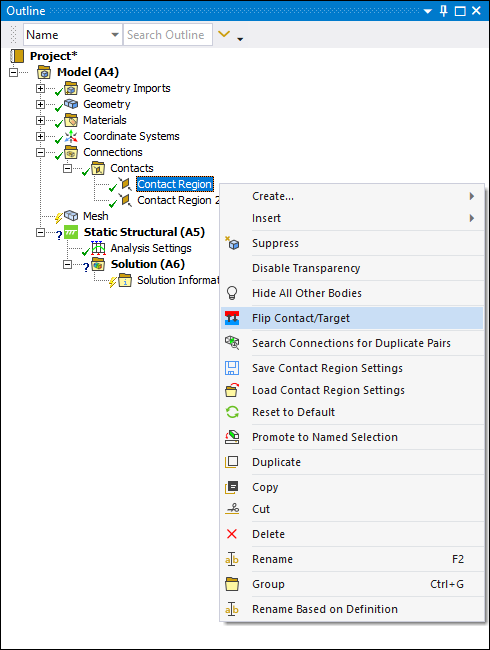
Flipping Contact and Target Scope Settings
A valuable feature available when using asymmetric contact is the ability to swap contact and target face or edge designations. To flip the scoping, right-click the desired connection and select . This is illustrated below for a single region. Note that you can select multiple connection objects to flip using the Ctrl or Shift keys.
Note: This feature is not applicable to Edge-to-Face contact where the edge is always designated as the contact and the face is always designated as the target.