Using a Dynamic Control object, the motion of a structure can be controlled by applying a dynamic force or moment at the structure's center of gravity, allowing it to move along a specified course or toward a given position or heading. The Aqwa solver uses a proportional-integral-derivative (PID) algorithm to determine the lateral forces and yaw moment to be applied, according to user-defined PID coefficients and the instantaneous distance/rotation offset from the target. For more information, see Ship Course Control and Floating Structure Dynamic Positioning System in the Aqwa Theory Manual.
To add a Dynamic Control object:
Select the time domain Hydrodynamic Response object in the Outline tree view.
Right-click the Hydrodynamic Response object and select >
or
In the Analysis toolbar, click Dynamic Control,
 .
.
Dynamic Control objects can only be added to Time Response analyses.
The Dynamic Control object has Visibility and Activity properties for showing/hiding and suppressing/un-suppressing the object in the current analysis.
- Structure
Defines the Part or Dynamic Point to apply the Dynamic Control to.
- Control Type
Defines the type of control system that you are modeling. This can be:
- the structure is pushed towards a fixed, straight-line course and heading.
- the structure is pushed towards a target point (fixed or moving) on the global XY plane.
- the structure is pushed towards a target point (fixed or moving) on the global XY plane, with a defined relative rotation between the structure and the target.
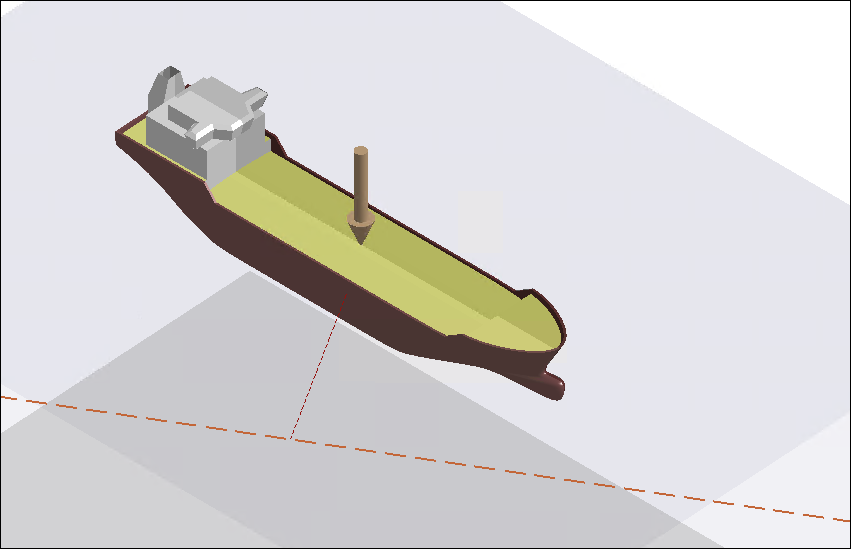
- Control Point
Defines the point that the Dynamic Control will try to move on to the target. In the Graphical Window, the Control Point is indicated by an orange downward-pointing arrow.
When the Control Type is set to Lateral Position Control or Lateral Position/Rotation Control, the Control Point on the selected Structure can be set to Structure Center of Gravity (default) or any Connection Point defined on the structure.
When the Control Type is Course Control, the Control Point can only be Structure Center of Gravity.
The properties for Target Definition depend on the selected Control Type.
Target Definition for Course Control
When the Control Type is set to Course Control, the following properties are available:
- Course Origin
The Course Origin can be set to:
. Where you will need to enter the and .
Any Fixed Point defined in the model. Where the Course Origin X and Course Origin Y fields display the position of the Fixed Point in the global XY plane.
- Course Heading (about Global Z)
Sets the course direction from the origin. The course extends to infinity in both directions.
In the Graphical Window, the Control Point, which is the Structure Center of Gravity, is indicated by an orange downward-pointing arrow. The defined course is shown as a long-dashed orange line across the global XY plane. The shortest distance from the Control Point to the defined course is shown as a short-dashed red line.
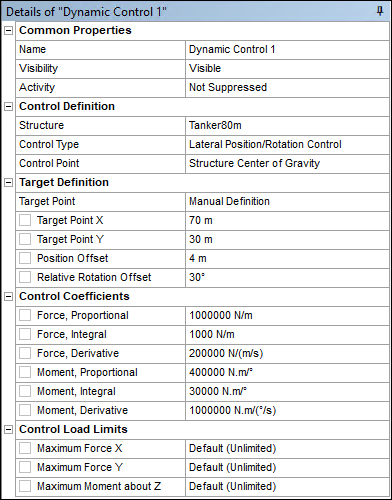
Target Definition for Lateral Position and Position/Rotation Control
When the Control Type is set to Lateral Position Control or Lateral Position/Rotation Control, the following properties are available:
- Target Point
The Target Point can be set to:
. Where you will need to enter Target Point X and Target Point Y.
Any Fixed Point or Dynamic Point defined in the model, any other structure's center of gravity, or a Connection Point defined on another structure. When one of these options is selected, the and fields display the initial position of the selected item in the global XY plane.
If the Target Point is set as a Dynamic Point, Connection Point, or another structure's center of gravity, it will move with that structure during the time response analysis.
- Position Offset
Defines the distance between the Control Point and the Target Point.
- Relative Rotation Offset
When the Control Type is set to Lateral Position/Rotation Control, you can also define a Relative Rotation Offset between the selected Structure and the Target Point. For a moving target, the rotation of the selected Structure will follow the target structure as the latter rotates.
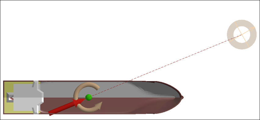
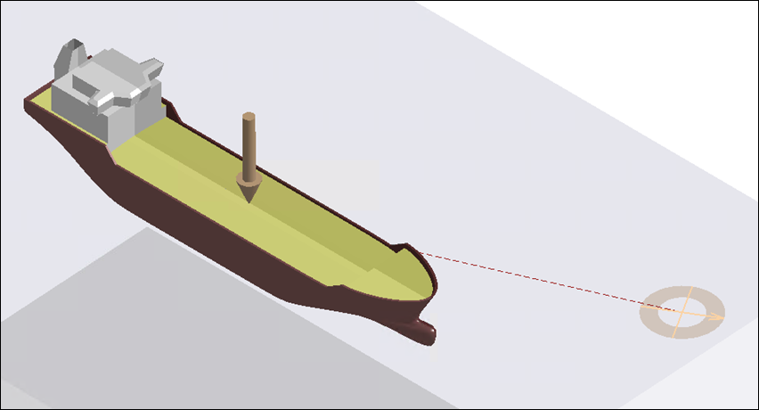
In the Graphical Window, the Control Point is indicated by an orange downwards-pointing arrow. The Target Point is shown by orange crosshairs in the global XY plane, with the shortest distance from the Control Point to the Target Point drawn as a red dashed line. The crosshairs will open out to indicate the defined Position Offset, and, when the Control Type is set to Lateral Position/Rotation Control, the crosshairs will rotate with a compass point to show the Relative Rotation Offset.
The lateral forces and yaw moment applied by a Dynamic Control object are functions of coefficients for the proportional, integral and derivative terms of the PID algorithm. The proportional term can be considered as a linear spring stiffness. The integral term often reduces the steady-state error between the structure and its target. The derivative term, as a function of the rate of change of the error, provides a degree of damping to the Dynamic Control load response.
Enter non-negative values in the Force, Proportional, Force, Integral and Force, Derivative fields. When the Control Type is set to Course Control or Lateral Position/Rotation Control, you should also define corresponding Moment coefficients.
By default, the forces and moment applied by a Dynamic Control are unlimited. However, where you have realistic data for the model - for example, the maximum power specifications of a vessel's Dynamic Positioning System (DPS) - you can define the Maximum Force X, Maximum Force Y, and (where applicable) the Maximum Moment about Z. Enter 0 in the appropriate field if you need to reset one of these to the Default (Unlimited) value.
When an Animation result is played in a Time Response Analysis, the Dynamic Control is drawn in the Graphical Window with a straight arrow indicating the instantaneous direction of the applied force vector at the structure's center of gravity, and (where applicable) a circular arrow showing the instantaneous direction of moment. These arrows are drawn in light orange, but if the applied force or moment reaches a defined Control Load Limit then the arrow color will change to red.