


VM-LSDYNA-SOLVE-063
VM-LSDYNA-SOLVE-063
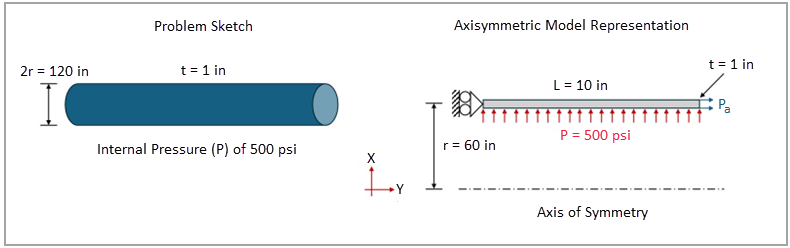
Cylindrical Vessel Under Internal Pressure
Overview
| Reference: | Timoshenko, S. (1955). Strength of materials: Part I, elementary theory and problems. D. Van Nostrand Co., p. 45, article 8. |
| Analysis Type(s): | Implicit Static Structural Analysis |
| Element Type(s): | 2D Axisymmetric Shell Elements |
| Input Files: | Link to Input Files Download Page |
Test Case
This test case models a long cylindrical vessel with closed ends, subjected to an internal
pressure ( ) of 500 psi. The vessel has a mean radius (
 ) of 60 in and thickness (
 ) of 1 in. The objective is to validate the circumferential
stress of the vessel.
) of 1 in. The objective is to validate the circumferential
stress of the vessel.
The 3D cylinder is modeled as an axisymmetric rectangular
cross-section representing the cylindrical shell. An axial pressure ( ) is used to simulate the effect of a closed end, while the opposite end has
its movement constrained in the axial direction. The axisymmetric model has an arbitrary
length of 10 in. See Figure 202.
) is used to simulate the effect of a closed end, while the opposite end has
its movement constrained in the axial direction. The axisymmetric model has an arbitrary
length of 10 in. See Figure 202.
This problem is also presented in test case VM13 in the Mechanical APDL Verification Manual.
Figure 202: Schematic of the test case, including domain geometry, main dimensions, and boundary conditions
The following table lists the main test case details using this system of units: length (in), time (s), mass (lbf-s2/in), force (lbf), and pressure (psi).
| Material Properties | Geometric Properties | Loading |
|---|---|---|
|
Vessel dimensions: length ( radius ( thickness ( |
Young’s modulus E = 3 ⋅ 107 psi Poisson’s ratio ν = 0.3 Density ρ = 7.33 ⋅ 10-4 lbf-s2/in4 |
Internal pressure
Axial displacement of one end
Axial pressure of opposite end
|


Analysis Assumptions and Modeling Notes
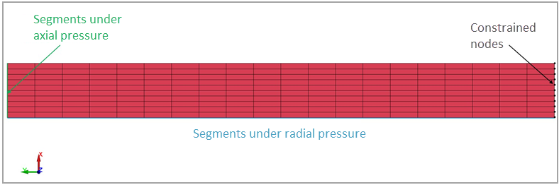
Figure 203: Model setup in LS-DYNA of the 2D axisymmetric analysis of cylindrical shell under pressure
To simulate the closed end effects on a cylindrical vessel, an axial pressure ( ) can be applied on the cross-section of the open end:

where
 is the internal pressure is the internal pressure |
 is the cross-sectional area of the vessel is the cross-sectional area of the vessel |
 is the cross-sectional area of the cylindrical shell is the cross-sectional area of the cylindrical shell |
 is the mean radius of the vessel is the mean radius of the vessel |
 is the vessel thickness is the vessel thickness |
Therefore, an axial pressure ( ) of 15,000 psi should be applied to simulate the effects of closed ends.
The tensile stress in the circumferential direction ( ) of a cylindrical pressure vessel with closed ends can be calculated as:

For the current test case, the tensile circumferential stress ( ) is 30,000 psi.
One part is defined to represent the axisymmetric vessel, being meshed with 2D shell elements. These elements use an axisymmetric shell element formulation (*SECTION_SOLID with ELFORM=15), which considers Y the axis of symmetry (shown in Figure 202). The keyword *BOUNDARY_SPC_NODE_SET is used to constrain the Y-translation for nodes of one end of the vessel. The set of element edges where the pressures would be applied are defined using *SET_SEGMENT. The internal pressure of 500 psi and axial pressure of 15,000 psi are applied using *LOAD_SEGMENT_SET on their respective segment sets. The keywords *CONTROL_IMPLICIT_DYNAMICS (IMASS=0) and *CONTROL_IMPLICIT_GENERAL (IMFLAG=1) are used to activate the implicit static structural analysis.
Results Comparison
The visualization of the final configuration of the cylindrical vessel under internal pressure can be performed by reading the d3plot file. To quantify the error between the theoretical and LS-DYNA results, the circumferential stress (Z-stress) and its relative error are calculated and shown in the following table. The mid-span element adjacent to the inner boundary is selected for the stress calculation. This comparison confirms stress agreement and validates the model.
| Results | Target | LS-DYNA Solver | Error (%) |
|---|---|---|---|
| Circumferential Stress (psi) | 30,000 | 30,016 | 0.05% |