EMSEL
EMSEL,
Type,Item,
Comp, VAL1,
VAL2, VAL3
Specifies conditions for selecting reinforcing
members or layers of shell sections.
TypeLabel identifying the type of specification:
S – Specify a new set of conditions (default). A – Specify an additional set of conditions and add it to the current set. U – Remove specified condition(s) from the current set. If the condition is not included in the current set, a warning message is issued, and the command is ignored. ALL – Set a condition to select all reinforcing members or shell layers. CLEAR – Remove the current set of conditions. STAT – Display the status of the current set of conditions. LIST – Display selected reinforcing members or shell layers based on the current set of conditions. ItemLabel identifying the selection item. See Table 122: EMSEL - Valid Type, Item and Component Labels.
Itemdefaults to REINF whenType= S, A, or U.Itemdefaults to ALL whenType= ALL, CLEAR, STAT, or LIST.For more information, see "Notes".
CompComponent label for selection and listing when
Type= S, A, U, or LIST. See Table 122: EMSEL - Valid Type, Item and Component Labels.For more information, see "Notes".
VAL1, VAL2, VAL3Input values on
ItemandCompwhenType= S, A, or U. See Table 123: EMSEL - Valid Input Values for a Component Label.
Table 122: EMSEL - Valid Type, Item and Component Labels
| General Type, Item and Component Labels | |||
|---|---|---|---|
| Type | Item | Comp | Description |
| S, A, U | REINF (default) | NUM (default) [a] | Global identifier (EGID) |
| LAYER | NUM (default) [a] | Layer number | |
| NAME | Layer name | ||
| LAST [b] | Last layer | ||
| MAX [c] | Maximum value of an element output | ||
| LIST [d] | ALL (default), REINF, LAYER | SEL (default) | Displays the list of selected members or layers. [e] |
| LAYER | STO [f] | Displays the list of stored layers (selected layers in SOLUTION (/SOLU)) for shell elements. | |
| STAT | ALL (default), REINF, LAYER | - | Displays the status of current conditions to be used for selecting reinforcing members or shell layers. |
[a] When Type = ALL, the conditions are specified by
Comp = NUM.
[b] When Type = S, Comp = LAST can
be used to select a single layer. When Type = A, the condition
is added to the current set, if other conditions exist.
[c] Comp = MAX is only supported when
Type = S, as only one layer is selected based on the
maximum value of specified output. Previous conditions are removed if they exist.
[d] Type = LIST is invalid in SOLUTION when
Comp = MAX to determine the output locations of shell
elements.
[e] Listing of selected layers based on Comp = MAX
calculation is not supported in SOLUTION.
Table 123: EMSEL - Valid Input Values for a Component Label
| Comp | VAL1 | VAL2 | VAL3 |
|---|---|---|---|
| NUM | Minimum value of selection range | Maximum value of selection range | Value increment within the specified range. Defaults to 1.
VAL3 cannot be negative. |
| NAME | String up to 32 characters | - | - |
| LAST | - | - | - |
| MAX [a] | S, EPEL, EPPL [b] | EQV [b] | - |
| S, EPEL, EPPL, EPCR, EPTH, EPTO, EPTT, FC [c] | X, Y, Z, XY, YZ, ZX, EQV [c] | - |
Notes
The EMSEL command manages a set of specified conditions to select a group of reinforcing members or layers of shell sections. The actual selection status is determined by the action commands for plotting (EPLOT, PLESOL and PLNSOL), printing (PRESOL and PRNSOL), or solution output (SOLVE) that follow the EMSEL command.
Example 16: Plotting a set of reinforcing members
The following command plots a set of reinforcing members based on global identifiers 1 through 3:
EMSEL,S,REINF,NUM,1,3
EPLOT
Example 17: Plotting a set of shell layers
The following set of commands plots a set of shell layers based on layer numbers 1 through 7:
EMSEL,S,LAYER,NUM,1,7
EPLOT
For Item = REINF:
EMSEL is valid only for the reinforcing elements generated via the mesh-independent method for defining reinforcing members in PREP7 (/PREP7) and POST1 (REINF263, REINF264, and REINF265).
For the standard method, you can use the LAYER command to select a reinforcing member in POST1. (LAYER is not valid in PREP7).
When using the mesh-independent method for defining reinforcing, the global identifier for a set of MESH200 elements (EGID) is transferred from the MESH200 elements to the reinforcing members (individual reinforcings) while the reinforcing elements (REINF
nnn) are generated (EREINF).For more information about using this command in a mesh-independent reinforcing analysis, see Selecting and Displaying Groups of Reinforcing Members in the Advanced Analysis Guide.
For Item = LAYER:
EMSEL is valid in PREP7, SOLUTION, and POST1 for shell sections.
In PREP7, the EMSEL command can be used in conjunction with the SECMODIF command to modify the properties of shell sections. Issue the EPLOT command in Power Graphics (/ESHAPE,1) to display the selected layers for 3D structural shell elements (SHELL181 and SHELL281).
In POST1, EMSEL can be used to review element outputs in the selected layers for 3D structural shell elements (SHELL181 and SHELL281).
The last EMSEL or LAYER command takes precedence for post-processing.
When
Comp= MAX, the maximum value in the current coordinate system (RSYS) is selected. If the maximum value is included in two or more layers, the lowest layer is selected.When the EMSEL command is used to process the nodal solution outputs and multiple layers are selected, the layer with lowest layer number is used for nodal averaging or element output, such as:
the plotting of shell element in plane shape (Full Graphics or Power Graphics with /ESHAPE,0)
the printing of nodal solutions.
If the LAYER command is issued prior to resetting the conditions (either through ALLSEL or EMSEL, CLEAR), the output of subsequent post-processing commands is determined by the last LAYER command. If LAYER was not issued prior to EMSEL, the default state (LAYER,0) is applied to the subsequent post-processing commands.
When displaying a contour plot for shell elements with stored layers in SOLUTION, any layers that are not stored are shown in a solid color with zero values for elements with KEYOPT(8) = 1 or 2. Issue the EMSEL command to hide the layers that are not stored. Elements with KEYOPT(8) = 0 display a single layer with total thickness, where the solution output from the stored layer is applied onto it.
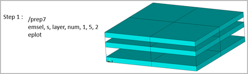
Figure 5: Select and display layers in PREP7 and POST1 shows how to select layers and display the selected layers using the EMSEL and EPLOT commands in PREP7 and POST1.
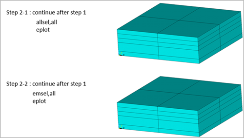
Figure 6: Selecting layers in PREP7 and POST1 shows how to select (or reselect) all layers with two different options in PREP7 and POST1.
In SOLUTION, EMSEL can be used to store element outputs at specified layers for 3D structural shell elements (SHELL181 and SHELL281).
When KEYOPT(8) = 0, you can store element outputs for a specific layer, instead of the default output locations (See SHELL181 and SHELL281 for default output locations). If multiple conditions are specified, the outputs for the layer with the lowest layer number are stored (even if all layers are specified).
When KEYOPT(8) = 1 or 2, you can store element outputs for selected layers using combined conditions (Comp = NUM, NAME, LAST and MAX), instead of the default output locations.
EMSEL retains the predefined conditions even when the ALLSEL, ALL command is issued. Issue EMSEL,CLEAR to remove the current set of selection conditions.
Static and transient analyses are supported, including multiple load steps and restart options. Analysis types that require downstream analysis or mode expansion are not supported.