


In addition to the large amount of data maintained for circuit cards, Ansys Sherlock generates a large amount of data when analysis tasks are executed. In most cases, Sherlock summarizes such data in graphical form to help users determine the real sources of problems. But, given the extensive nature of the analysis performed, even the summary graphics can be overwhelming. More importantly, analysis results might be used for subsequent analysis or reporting tasks performed outside of Sherlock. For these reasons, Sherlock has features designed to allow users to export data in various formats including:
Printable report files (PDF)
Graphical chart image files (PNG)
Tabular data files (CSV)
This document shows how each of these types of files can be exported and integrated with other user data.
Note: The examples shown in this document are based on the Sample Project provided as part of the Sherlock Tutorial package as discussed in the Project Overview lesson.
In this section, the following topics are covered:
The fastest and easiest way to export project data is to generate a report file. Report files are formatted as PDF documents based on a collection of predefined report objects that can be selectively chosen by the user. Reports can be generated for an entire project or for each circuit card assembly. Report objects are defined that can be used to:
Provide an overview of the analysis tasks performed
Describe the circuit cards analyzed
Document the Life Cycle assumptions
Show graphical results
List the most important circuit card issues
Sherlock report files are formatted so that they can be used as preliminary, intermediate or final reports, depending on specific user needs.
To generate a Project Report, right-click the Report entry located in the Results Folder of the Project Tree and select the Generate CCA Report menu option. After selecting Generate Report, the Report Properties dialog will appear.
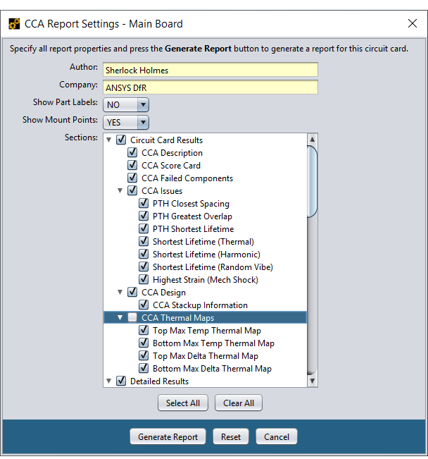
The Report Properties dialog allows you to select the report sections to be included in the report. In this project report example, the report will include an initial set of explanatory sections that describe the analysis tasks performed by Sherlock, followed by a complete list of the Life Cycle Phases and Events defined for this project.
After those project-level sections, the report will include circuit-card level results for each of the circuit cards defined in the project. Depending on the number of circuit cards contained in the project and your reporting needs, you can select exactly which CCA data should be included for each circuit card.
When generating a circuit card report instead of a project report, on the Circuit Card Results and Circuit Card Details will be available for selection and the report will be limited to the given circuit card. Whereas a project report will provide details for all circuit cards. The Circuit Card Details section found in the circuit card report will include all the select analysis layers generated for each circuit card.
As shown here, the CCA Thermal Maps are NOT included in the report
Although the section list is very long, it is relatively easy to navigate and select desired sections. The check box to the left of each entry indicates whether it is included in the report. The only important thing to remember is that if you deselect an item in the tree, then all items below that item will be excluded from the report as well, regardless of their individual settings. This allows you to quickly include or exclude report sections without having to change all the individual settings below that item.
When the Generate Report button is pressed Sherlock will generate a PDF report file containing the selected sections, based on the current analysis inputs and results. A copy of the report file will be kept in the Sherlock project or circuit card directory for subsequent viewing but will be automatically cleared if any Sherlock inputs are changed.
Note: If you want to maintain a collection of reports that address different topics or that cover different inputs or analysis results, then you should save of copy of the PDF report to your own directory and change the file name accordingly. Sherlock only keeps the most recently generated report for a given project or circuit card.
By creating their own Report Definition File, advanced users can customize the following report characteristics:
Logo image, title, keywords
Section headers, descriptive text, and formatting
The order that sections are published
Define additional sections
This allows users to generate reports bearing the logo of their organization, that include organization-specific information, and that present data in a user-defined order.
Report Definition Files are formatted as an XML file, containing a collection of predefined tags, as shown here:
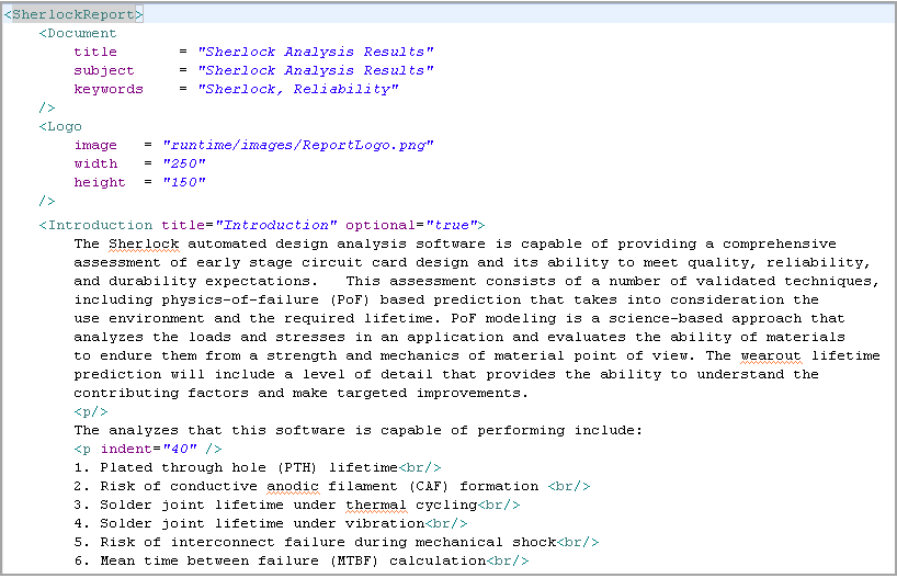
The easiest way to create a custom Report Definition File is to copy the standard Report.xml file for a project report, or the standard CCAReport.xml file for a CCA report, or the standard ResultsReport.xml file for archived results reports, contained in the config sub-directory of the Sherlock installation directory (usually c:\Program Files\Ansys Inc\v252\sherlock) to the Sherlock User Data Directory. Whenever Sherlock generates a report, any report definition file located in the Sherlock User Data Directory will be used instead of the standard report definition file located in the Sherlock Installation Directory. This allow users to make custom changes to their reports without fear of causing permanent damage. If the report doesn't turn out the way you like, just remove the local copy of the report definition file and Sherlock will revert to the standard definition file.
The order in which sections are created within the report are the same as they are defined in the XML file. When moving a section, be sure to copy the entire section defined by the beginning and ending XML tags.
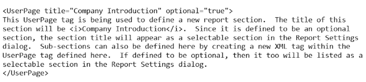
Additional report sections for static text may also be included. Create a new unique tag with title and optional attributes, define the text, then end the section with the appropriate ending tag. Any section that is defined with an optional value of true will be listed in Report Settings dialog. If a given section is not optional, it will not be listed in the dialog but will always appear in the created report.
Example user-defined section:
Each report section supports the following HTML tags to adjust formatting.
<br/> - adds a newline to the report
<p/> - begins a new paragraph. Optionally may specify the attribute indent to specify the indent of the paragraph (example: <p indent="40" />)
<b>text</b> - displays the text between the tags in bold.
<i>text</i> - displays the text between the tags in italics.
It is beyond the scope of this lesson to explain how XML files are properly formatted and edited. Users familiar with maintaining XML documents should have no problem modifying the standard report XML files for their own needs. Users new to XML formatted files should contact Ansys Technical Support for help in creating customized reports.
Ansys Sherlock generates and displays several graphical layers and charts to show circuit card designs and analysis results. Many of these graphical outputs can be included in the PDF report by selecting the appropriate section. As a convenience, all graphical data shown in Sherlock can also be exported as image files with just a few mouse clicks, as we describe in this section.
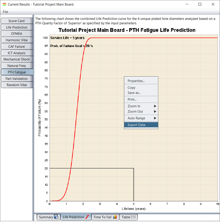
Chart data can be exported as a Comma Separated Value (CSV) file, that can be subsequently imported into any spreadsheet or database application for further review or processing. To do so, simply choose the Export Data menu option from the chart's right-mouse menu. Here, a file chooser dialog will appear allowing you to specify the name and location of the export file to be created. By default, the chart title is used as the file name, but it is easily changed to suit your purposes.
In some cases you may want to modify or customize the chart for a specific purposes, such as including it in a presentation or paper. If so, select the Properties... menu option from the chart's right-mouse menu to display the Chart Properties dialog.
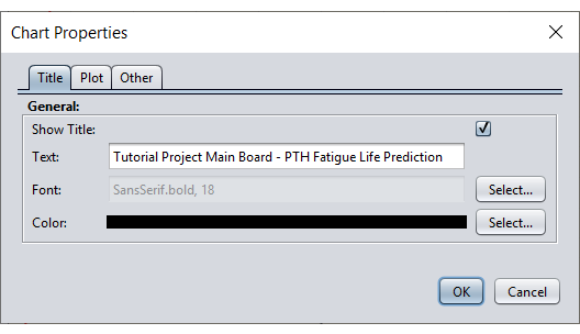
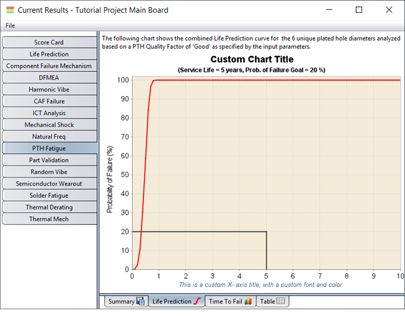
The Chart Properties dialog allows you to easily change the chart title, axes titles and axes format. When combined with the built-in zoom and auto-range features, you can easily create a custom chart such as the one shown below in which we modified the chart title, X-axis title and the data ranges.
Graphics are very useful for summarizing and analyzing large data sets but there are times when you need to analyze the results in more detail or use them as input for other analysis tasks performed outside of Sherlock. To satisfy such needs, Sherlock provides the ability to export data from the following tables to a CSV file:
Parts List
Stackup Data
Analysis Results
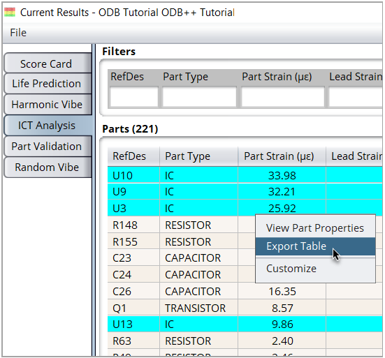
To export table data, open the table of interest in Sherlock and do the following:
If you wish to export only a selected set of table rows, highlight the rows now. Hold the Shift key and click to select a group of adjacent rows. Or, hold the Ctrl key and click to select individual rows.
If you have selected multiple rows, right-click any highlighted row and select the appropriate export option from the context menu (as shown below), such as Export Parts List, Export Stackup Data, or Export Table. If you intend to export all rows, simply right-click any row and select the export option in the context menu. The export dialog will open.
In the export dialog shown below, select the export properties:
All Rows: Select this option to export all table rows.
Columns: Specify which columns you wish to export. Select All Columns or manually select which columns to export by holding the Shift or Ctrl key while you click specific columns.
Selected Rows: Select this option to export only the rows you selected earlier in step 1.
Browse: Use the Browse button to specify the name and location of the file to be created, or enter it directly in the text field.
Column Delimiter: Select the column delimiter for the exported file: Comma, Semicolon, Tab, or Space.
UTF-8: Enable this option so that special Unicode characters (like με) are displayed correctly when the file is opened in an external application such as Excel.
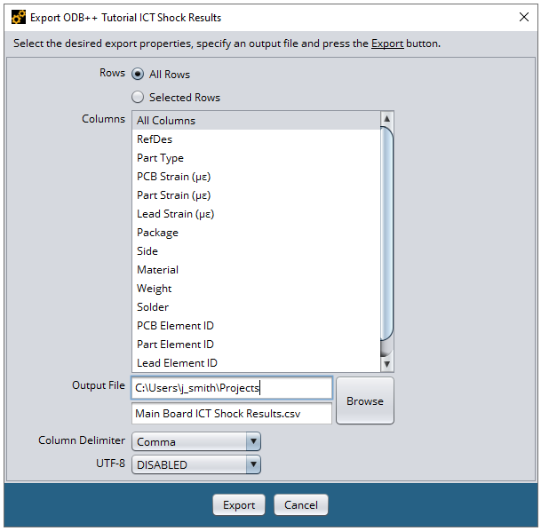
When you click the Export button, Sherlock exports the data as a CSV file in the location you specified.